Here is some explanation about the two pinouts that I posted. It’s been a while since I made the cable so forgive me if I keep coming back to this forum to make edits and corrections to this post:
The first pinout diagram I posted is the microphone cable of the Retevis RA-25 which is functionally the same as the AT-779uv. I included that diagram because cable-wise, it should be a match to the microphone pinout that I have on my AT-779uv. I purchased the DigiRig cable for the AT-D578 because of the similarity in wire pinouts and because it was a readily available cable. That is the cable I modified to get it to work with the AT-779uv. The signals listed for the D578 aren’t all identical to those on the 779uv, but the cable will work with the only modification being the addition of a TRS with the tip going to pin 4 on the D578’s DigiRig cable. To do that I carefully removed some insulation from the cable about an inch or so from the RJ45 connector. Looking at the RJ45 connector on the Digirig cable I could see that it was the red wire on pin 4, so I then removed a little insulation from the red wire and soldered another wire to it, which went to the tip of the TRS connector. You are correct that the cable you need has to have audio input from the speaker jack on the back of the radio. The tip of the TRS cable supplies audio from the radio’s speaker output to the DigiRig because the tips of both TRS and TRRS are connected together. Short answer: The second pinout that I posted will work. Your diagram is a bit confusing to me. I may have muddied the waters by using the term cat5 cable when I meant the RJ45 connector on the DigiRig cable I was modifying. Apologies for that. As a last note, my AT-779UV doesn’t work with VOX despite claiming to have VOX support in the documentation, so I had to use software capable of sending the PTT command by RTS. Since the advent of the DigiRig Lite, it should also work with software that doesn’t support RTS, like APRSDroid, for example. I hope this answered your question. Good luck. - Jon
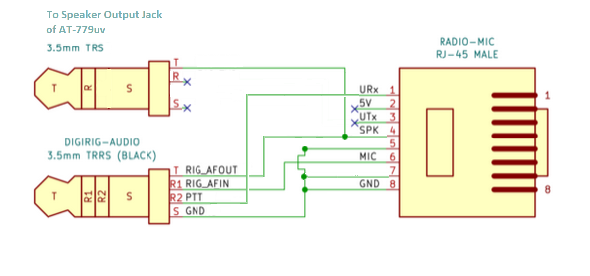
I believe this to be a correct diagram of the cable I have. Let me know if you have any questions. I have used it successfully with Direwolf and had it running with a Digipeater and iGate.
- Jon
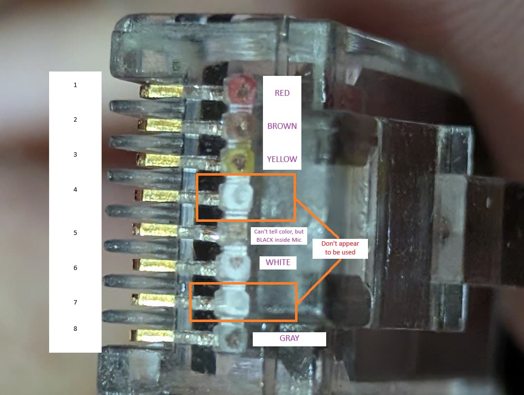
I don’t know if I’ve got an off cable or what. This is a closeup of the RJ45:
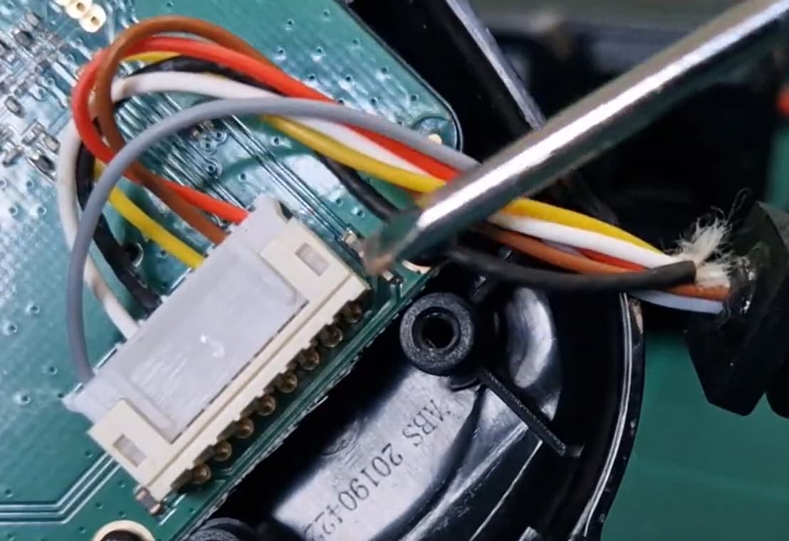
And this is from a screencap of someone opening up the microphone:
Based on the colors and the order, pin 4 and 7 don’t appear to have anything connected in the mic. I’m assuming since your cable works though that there’s some connection in the radio that makes these possible, and I think that’s what was confusing me. I’m going to pull all the cabling out again later this evening and try again to wire it the way you have it setup, see if I can get it to work.
Thank you for your help!
Sorry for any confusion I may have caused, but I didn’t modify the microphone cable. I modified an existing DigiRig cable with a close or similar pinout to what I needed. That made the actual cable build very simple. I just took the Anytone AT-D578 DigiRig cable and added a pigtail TRS about a foot long with the wire from the RJ45 Pin 4 connected to the tip of the TRS, which plugs into the speaker jack on the back of the radio.
No, I was making assumptions that the mic cable had all the connections that were being used, but when I thought about it I realized just because the mic cable didn’t have those pins in use didn’t mean a digirig cable wouldn’t use them.
So, going by your photos it APPEARS to me that the color scheme on the microphone looks like it matches my first diagram which is for the microphone of the RA-25. So far, so good. It should also be correct for the AT-779uv. Note: The radio doesn’t use Pin 4, but that works in our favor. We can use the existing wire from the RJ45 to create a connection between the DigiRig’s Audio In and the Radio’s Audio out jack. Given your color scheme, you should have the following connections:
RJ45----------------TRRS-----------TRS
1 RED ---------------R2
2 BROWN —X
3 YELLOW --X
4 WHITE ----X------T---------------T
5 BLACK ------------S
6 WHITE ------------R1
7 WHITE ------------S
8 GRAY --------------S
Pins 2 and 3 aren’t used by the DigiRig in this version of the cable. Pin 4 isn’t used by the radio. You’ll have to figure out which white wire is which. I guess you could stick a pin in each, one at a time and check continuity between the RJ45 pin 4 and the pin with a multimeter until you find the correct wire. Just make sure you seal the pin holes so nothing shorts out later. If it turns out that there is no white wire connected to pin 4, like it’s cut off at the RJ45 connector, you’ll have to use an external wire to connect to two tips together.
One note on VOX, I was able to enable it in the settings, but then you still have to manually turn it on by holding down the V/M key when it’s already up and running. This has to be done each time you turn the machine back on. Caused me issues the first few tries of my original cable, because I didn’t realize you had to turn it on in settings and with the V/M button.
The PTT is via Serial Interface - I built a simple and cheap interface for a legacy TNC using a Arduino Nano
The Arduino Sketch is detailed, along with info on my findings related to the serial protocol here:
David
KZ4TG
Thanks for that information. ![]()
I wasn’t aware of that before.
- Jon
Nice work! Thanks for including that information. ![]()
- Jon
OK, I think I have it working. Unfortunately, my antenna is just barely receiving the replies and I think the signal is too weak to do anything with it. I am going to work with a local ham to see if I can try a test connection over simplex with him.
But, this is what worked for me. I don’t have a Digirig, this is straight from the AT-779UV to my laptop running Direwolf and Winlink.
I see/hear the transmission going out, I can hear a faint reply from the node I’m trying to connect to, and I can see that the incoming signal is heard from the laptop.
So here is the final wiring diagram I’m using:
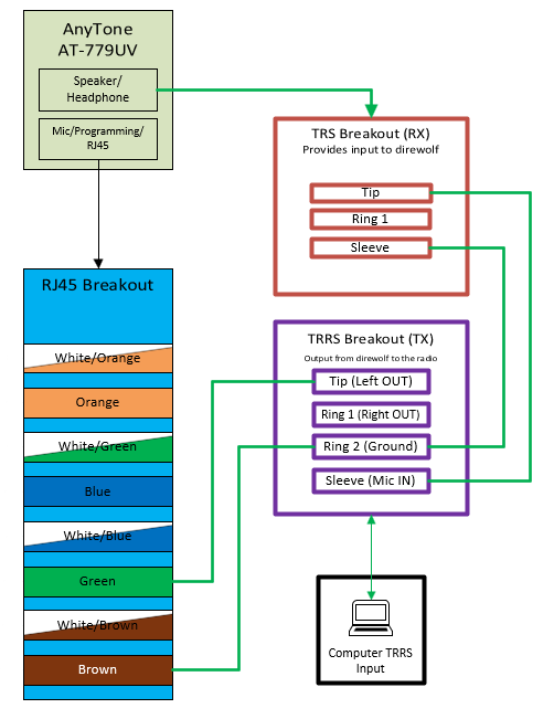
kk7npk, I did try starting with your diagrams, and it wasn’t working for my cable setup. So I started fresh, using a multimeter to verify the output from the TRS headphone/speaker jack of the radio and then verifying the output from the TRRS jack of the laptop.
For now I’m going to tentatively say this is working, and thanks for your help!
I bought a £4 RJ45 extension cable on ebay (RJ45 Male to Female Ethernet Network Screw Panel Mount Extension Cable - 0.3m) and this extends the mic. I have cut into the cable and switched pins 1 (Rx),3 (Tx), 5 (MicGnd) and 6 (Mic) to a UART to TTL. I now have a switch to select between PC and MIC. I now need to work out the codes that the MIC would send via the serial to control the rig. I believe that the FLDIGI CAT codes will not work with the AT779UV, but I will keep trying…
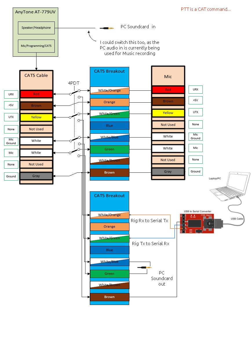
I don’t believe that the AT779UV has any CAT control functionality. It’s a very basic radio with not serial interface. You can use something like a DigiRig to send data through it over RF, but you can’t control the radio itself using CAT control. You have to manually change frequencies, etc.
Sorry if I gave the impression that it could be controlled remotely.
Best of luck.
- Jon
Thanks for the post Jon, I agree that the AT779UV doesn’t have the standard CAT remote comms, but I can now control the rig from my PC, as I can automate all the mic-button presses. I will either write my own FLDIGI program (not ideal) or write something that receives the FLDIGI commands and translates them to the serial that the mic would send (preferred).
The main requirement is PTT, which was easy like UP, DN, MAIN and MON, the fun comes with translating the frequency, and SQL. I will post all achievements here to help other AT779UV/Digirig users.
Phil
sweet!
if you get it all ‘lined out’ you can create a definition file for either fldigi or hamlib.
good luck
![]()
kb0wlf
Unfortunately it was not as simple as creating a definition file for fldigi or hamlib, as setting/changing the frequency for most rigs is a single command, but replicating the AT779UV mic buttons (using KZ4TG’s protocol between AnyTone AT779-UV Mic and Radio) requires each number to be pressed and released one at a time, as if you are pressing the number buttons.
So, to make fldigi send messages to the AT779UV I needed to use FLRIG, which sends codes to the serial. I selected the Yaesu FT817 rig codes, as it was the simplest, I built a C++ translator that listens to the code from FLRIG and translates this to what the mic would send. Just PTT and the numbers for frequency change for now. FLDIGI can be set to talk to FLDIGI so I can use FLDIGI to change the frequency on the rig and to automate the PTT for when FLDIGI is sending data.
It all works, but has a few issues that I need to decide whether to fix. If anyone is interested in collaborating on this project please let me know. Currently it is on Linux, the GUI C++ program automatically creates the virtual serial ports to send and receive to the radio, automatically opens and closes FLRIG and FLDIGI.
I am happy to provide the cpp code if anyone wants and am happy to explain the difficulties and issues.
As yet, I have no RTTY users nearby and am not aware of any RTTY repeaters or gateways to extend my range. I’ll let you know here if anything changes.
This is an image of my desktop with the FLDIGI, FLRIG and my program (rig1)…
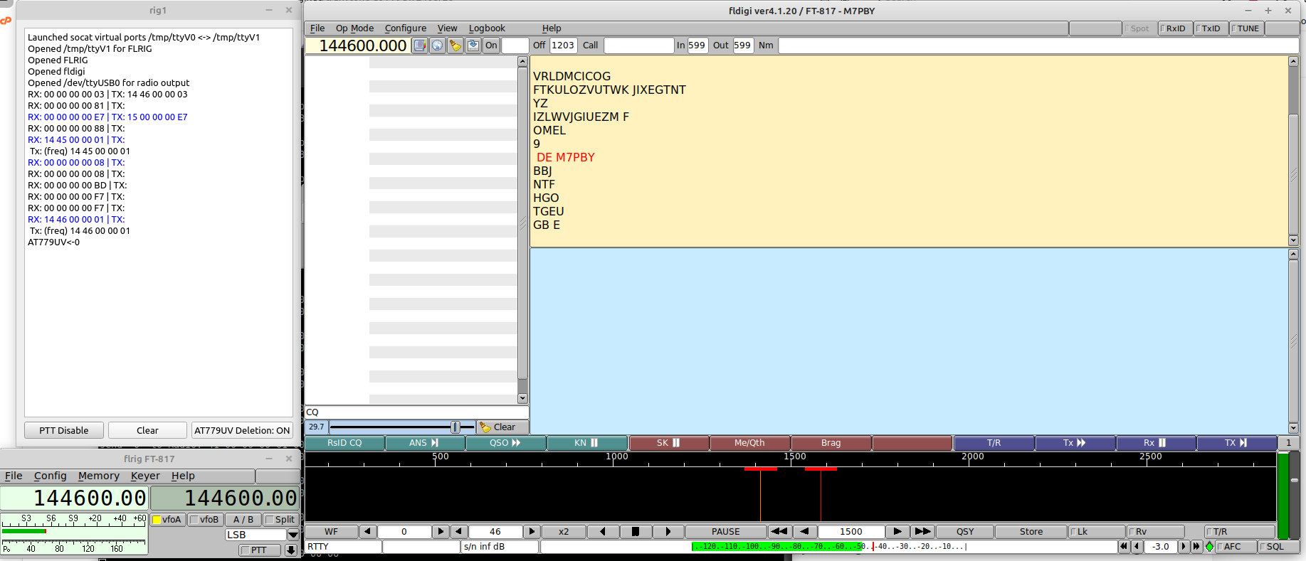
73s M7PBY
Is there gonna be an official cable for this?
It’s a possibility. I’ll make an announcement here and in the email list if/when it becomes available in store.