Based on the below information, the Digirig audio cable will look like this:
DB26 pin 8 (Audio Out) → 3.5mm TRRS tip (RIG_AFOUT)
DB26 pin 7 (MIC +) → 3.5mm TRRS ring 1 (RIG_AFIN)
DB26 pin 2 (PTT Input) → 3.5mm TRRS ring 2 (RIG_PTT)
DB26 pin 5 (Ground) → 3.5mm TRRS sleeve (GND)
DB26 pin 16 (MIC -) → DB26 pin 5 (Ground)
For serial connection if used:
DB26 pin 4 (Serial RX) → 3.5mm TRRS tip (RIG_RXD)
DB26 pin 14 (Serial TX) → 3.5mm TRRS ring 1 (RIG_TXD)
DB26 pin 15 (Ground) → 3.5mm TRRS sleeve (GND)
Serial connection requires Digirig Mobile, configuration will have to be confirmed, but likely logic levels.
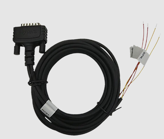
Hytera PC91 data cable
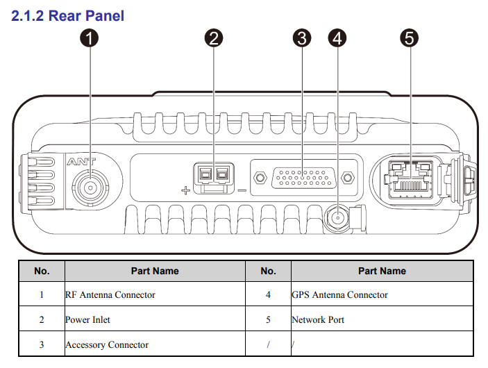
Hytera HM785 DB26 pinout (Need to confirm)
| Pin | Function | Description |
|---|---|---|
| 1 | Accessory Detection 1 | Used for accessory identification. Grounding this pin can enable specific accessory settings configured in the CPS. |
| 2 | PTT Input | Low-level input for an external Push-to-Talk (PTT) switch. |
| 3 | Handset Audio Output | Analog audio output for accessories like a handset. |
| 4 | USB_D- / Serial RX | Used for the USB programming cable and as a serial receive (RX) line. |
| 5 | Ground (GND) | Primary grounding point for the accessory connector. |
| 6 | Power Switch | An active jumper between this pin and pin 13 is used to enable the external speaker and disable the internal speaker. |
| 7 | MIC + / AUX Differential | Positive input for the external microphone or auxiliary differential audio input. |
| 8 | Audio Out | Analog audio output for accessories. Load resistor must be greater than 1kΩ. |
| 9 | Speaker Ground | The negative pole (—) for the external speaker. |
| 10 | Accessory Detection 2 | Used in combination with Pin 1 for accessory identification. |
| 11 | Remote Monitor | Can be configured via CPS to monitor activity. |
| 12 | TX Request / External Alarm Reset | Can be configured via CPS for a transmit request or to reset an external alarm. |
| 13 | External Audio Enable | When jumped with pin 6, this pin enables the external speaker and disables the internal one. |
| 14 | USB_D+ / Serial TX | Used for the USB programming cable and as a serial transmit (TX) line. |
| 15 | Ground (GND) | Secondary grounding point. |
| 16 | MIC - / AUX Differential | Negative input for the external microphone or auxiliary differential audio input. |
| 17 | Audio Mute | Used to mute the audio output. |
| 18 | Speaker Positive | The positive pole (+) for the external speaker. |
| 19 | IGN / External Alarm Input | Ignition sense input or external alarm input, configurable via CPS. |
| 20 | Power Output (+5V) | Provides a +5V power supply to accessories. |
| 21 | Digital I/O | General purpose configurable digital input/output (I/O). |
| 22 | Digital I/O | General purpose configurable digital input/output (I/O). |
| 23 | Digital I/O | General purpose configurable digital input/output (I/O). |
| 24 | Auxiliary Audio Out A | Can be configured via CPS for audio playback. |
| 25 | Auxiliary Audio Out B | Can be configured via CPS for audio playback. |
| 26 | Ground (GND) | Another grounding point. |