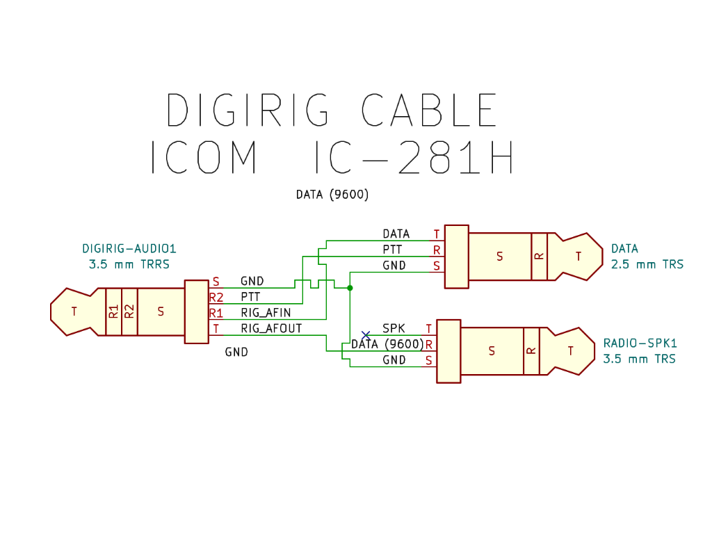
The 9600 baud Digirig audio cable will look like this:
DATA 2.5mm TRRS tip (Data input) → 3.5mm TRRS ring 1 (RIG_AFIN)
DATA 2.5mm TRRS ring (PTT) → 3.5mm TRRS ring 2 (RIG_PTT)
DATA 2.5mm TRRS sleeve (GND) → 3.5mm TRRS sleeve (GND)
SP 3.5mm TRRS ring (GND) → No Connection
SP 3.5mm TRRS ring (GND) → 3.5mm TRRS tip (RIG_AFOUT)
SP 3.5mm TRRS sleeve (GND) → 3.5mm TRRS sleeve (GND)
9600 baud audio path is also suitable for standard 1200 baud based digital modes.
NOTE for 9600 bps operation:
• If the transceiver does not transmit (the transmit indicator flashes or does not illuminate), the input level may be higher.
• If the re-try function is activated frequently, the input level may be lower.
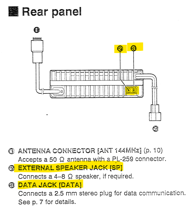
Operation:
Connect a TNC to the transceiver’s [SP] and [DATA] jacks.
Set the operating frequency. Push and hold [LOW-DATA] for 1 sec. to select data mode.
• “DATA” appears.
• The microphone signals are cut from the modulation circuit while in data mode.
Control the transceiver from a personal computer, etc.
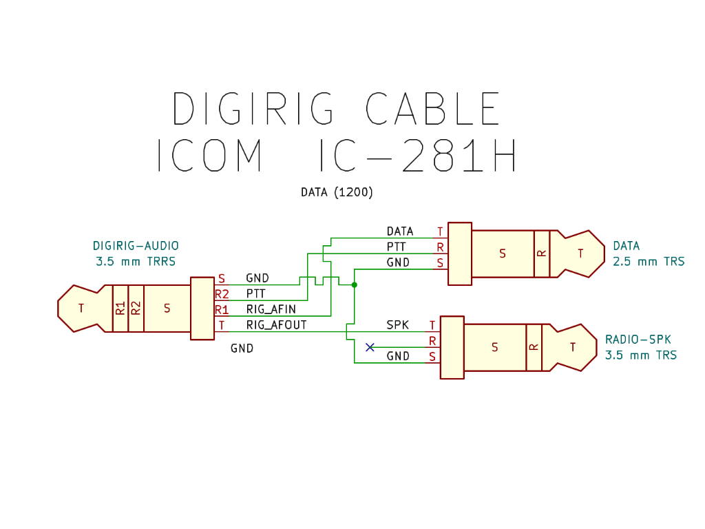
I just got a DigiRig, and I have an old ICOM IC-281H. I have homebrewed my own cable. I decided to make a nice Schematic diagram, like the other DigiRig diagrams, for the cables in the store. While I was looking for one, I found that the ICOM RJ45 cable works for a 1200-baud interface. I went ahead and made a couple of cables of my own, and wanted to share the diagram.
If you want to take advantage of the built-in 9600-baud interface on the IC-281H, you will need a different cable; just swap the T wire with the R wire on the 3.5 mm plug.
You might be able to make a switchable cable to swap the lines, but given the cost of the pieces, I think it’s cheap enough to just make a second cable. Additionally, I am planning on leaving it plugged in, so I don’t need to change modes, it will be one or the other for me.