This mic schematic landed in my inbox:
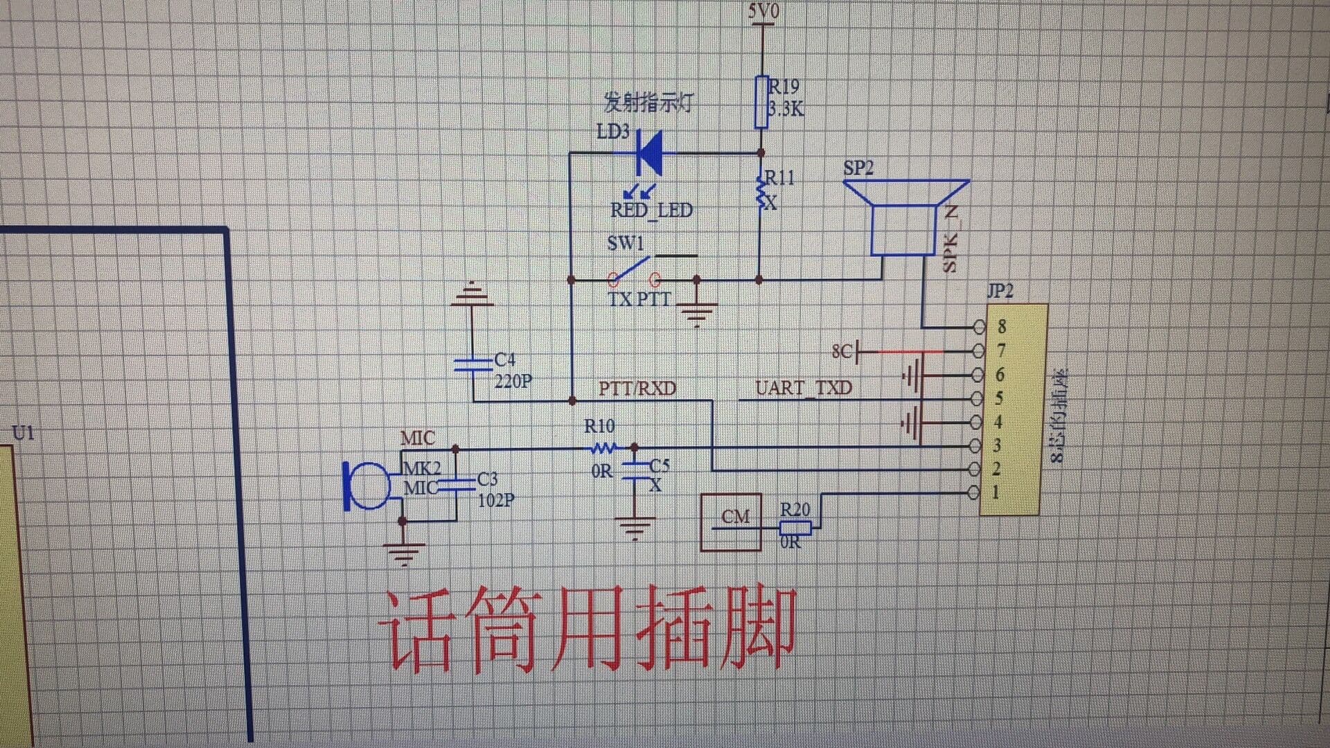
This pinout doesn’t match any of the pre-made cable available in store at the time of this post. It doesn’t even match other RJ45 mic pinouts used in Retevis radios. Use continuity tester between radio’s chassis (ground pin or shield of antenna’s connector) and pins on RJ-45 mic socket to find pins #4 & #6 to confirm direction of the pin numbers.
With that in mind the audio/PTT cable will look like this:
RJ-45 pin 8 (SPK_N) → 3.5mm TRRS tip (RIG_AFOUT)
RJ-45 pin 3 (MIC) → 3.5mm TRRS ring 1 (RIG_AFIN)
RJ-45 pin 2 (PTT) → 3.5mm TRRS ring 2 (RIG_PTT)
RJ-45 pin 4 (GND) → 3.5mm TRRS sleeve (GND)
RJ-45 pin 6 (GND) → 3.5mm TRRS sleeve (GND)
For serial cable (programming? CAT?) connect as follows:
RJ-45 pin 2 (RXD) → 3.5mm TRRS tip (RIG_RXD)
RJ-45 pin 5 (UART_TXD) → 3.5mm TRRS ring 1 (RIG_RXD)
RJ-45 pin 4 (GND) → 3.5mm TRRS sleeve (GND)
RJ-45 pin 6 (GND) → 3.5mm TRRS sleeve (GND)
Please report your results if you end up making the cable(s).