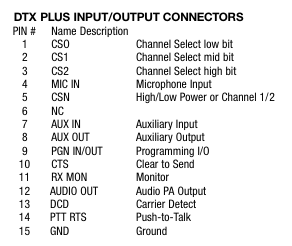
Not sure if 7 AUX IN and 8 AUX OUT are for the audio. If they are then they are the preferred option. If not, then 4 MIC IN and 12 AUDIO OUT are a fallback choice for audio.
Pin 7 or 4 → 3.5mm TRRS ring 1 (RIG_AFIN)
Pin 8 or 12 → 3.5mm TRRS tip (RIG_AFOUT)
Pin 14 → 3.5mm TRRS ring 2 (RIG_PTT)
Pin 15 → 3.5mm TRRS sleeve (GND)
There may be a possibility for interfacing Digirig’s serial port with pin 9 for programming (CI-V?), but that needs more documentation on this functionality of the transceiver.
and to connect things this way within the RJ-45 to DB-15 adapter:
RJ-45                           Connects to
Adapter                         Ritron
Terminal  Wire Function         DB-15 Pin       Purpose
-------------------------------------------------------------------------
  4       Ground (GND)          15 (GND)        Common system ground
  6       PTT (Push-to-Talk)    14 (PTT)        Drops to initiate keying
  5       Transmit Audio         7 (XmtAudio)   Play .wav audio signal
Google Gemini believes that the AUX IN port is correct, not MIC IN. In its words, “The AUX IN path is designed specifically for line-level data devices, telemetry modems, and external sound systems. The MIC IN path is tailored exclusively for an electret or dynamic voice microphone capsule.”
I do not believe that the Ritron DTX+ HP Transceiver supports 3rd-party programming. It does support some programming with proprietary Ritron software and, within that, we can specify 8 selectable channels (frequencies) that it can transmit on. The 8 available channels map out across the DB-15 pins 1, 2, and 3 as follows:
Chnl  CS2 (Pin 3)  CS1 (Pin 2)  CS0 (Pin 1)   Action
1     0 (GND)      0 (GND)      0 (GND)       Tie all three pins directly to Ground (Pin 15)
2     0 (GND)      0 (GND)      1 (Open)      Tie Pin 2 & 3 to Ground; leave Pin 1 disconnected
3     0 (GND)      1 (Open)     0 (GND)       Tie Pin 1 & 3 to Ground; leave Pin 2 disconnected
4     0 (GND)      1 (Open)     1 (Open)      Tie Pin 3 to Ground; leave Pin 1 & 2 disconnected
5     1 (Open)     0 (GND)      0 (GND)       Tie Pin 1 & 2 to Ground; leave Pin 3 disconnected
6     1 (Open)     0 (GND)      1 (Open)      Tie Pin 2 to Ground; leave Pin 1 & 3 disconnected
7     1 (Open)     1 (Open)     0 (GND)       Tie Pin 1 to Ground; leave Pin 2 & 3 disconnected
8     1 (Open)     1 (Open)     1 (Open)
Our intention is to program the frequency that we need on channel 8 and leave those pins alone.
We have already ordered the DigiRig parts and look forward to testing it out ASAP.
I wanted to post this update because I think that Gemini had the channel selection pins reversed earlier. I believe that the correct 8 channels map across the DB-15 pins 1, 2, and 3 as follows:
Chnl  CS2 (Pin 3)  CS1 (Pin 2)  CS0 (Pin 1)   Action
1     0 (Open)     0 (Open)     0 (Open)      Leave all three pins completely disconnected
2     0 (Open)     0 (Open)     1 (GND)       Tie Pin 1 to Ground; leave Pin 2 & 3 disconnected
3     0 (Open)     1 (GND)      0 (Open)      Tie Pin 2 to Ground; leave Pin 1 & 3 disconnected
4     0 (Open)     1 (GND)      1 (GND)       Tie Pin 1 & 2 to Ground; leave Pin 3 disconnected
5     1 (GND)      0 (Open)     0 (Open)      Tie Pin 3 to Ground; leave Pin 1 & 2 disconnected
6     1 (GND)      0 (Open)     1 (GND)       Tie Pin 1 & 3 to Ground; leave Pin 2 disconnected
7     1 (GND)      1 (GND)      0 (Open)      Tie Pin 2 & 3 to Ground; leave Pin 1 disconnected
8     1 (GND)      1 (GND)      1 (GND)       Tie all three pins directly to Ground (Pin 15)