It is quite trivial to make a homebrew cable. Typically I recommend sourcing an inexpensive speaker/mic and salvaging connector and wiring from it. The build then consists of just adding 3.5mm TRRS jack for the Digirig side and avoids potentially intricate soldering project on the transceiver end. In this case, however, I couldn’t find any cheap speaker/mic listings so a build from scratch may be more economical.
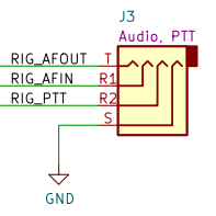
For reference, the pinout on Digirig’s side (rev 1.6 or later) looks like this:
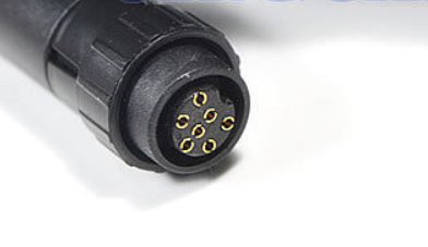
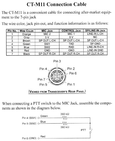
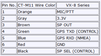
I am just trying to figure out how to connect the 7-pin jack to the TRRS jack. I guess the green wire (SW1) of the 7-pin jack goes to the tip of the TRRS connector, the blue one (SW2) to the firts ring (R1) and the red wire (GND) to ground (S)?
I wonder which cable from the 7-pin connector (PTT) should be connected to the second ring (R2) ? Could it be the orange (MIC) wire?
Has anybody done this before and could give me some tips?
Now I have bought the 390K resistors and soldered everything as implied above but I could not get it to work. According to your video (https://www.youtube.com/watch?v=1EtrkyisCnc) I have installed WSJT and in the settings menu I configured RST, the usb-port and the digirig soundcard but the PTT test failed. I futher followed your instruction on debugging the cable to the HT (VX-8). Shortening ring_2 (RIG_PTT) to ground did not get the HT to transmit. After that I rechecked all the connections and cables again and they seem to be fine.
While checking the cable connections I realized that shortening ring_1 (RIG_AFIN = orange cable) to ground gets the HT to transmitt! Not sure what is going on here - could it be that the CT-M11 info is wrong?
I found another connection layout for the VX-8 here: Reverse Engineering the Yaesu VX-8DR GPS Interface | Lingnik : Taylor J. Meek. There also the orange cable is used for transmitting. Any clues what’s wrong here?
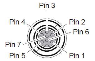
I’d suggest confirming the connections based on pin numbers and not the coloring of the wires.
You can check the continuity from the connector on the HT’s side to where you solder.
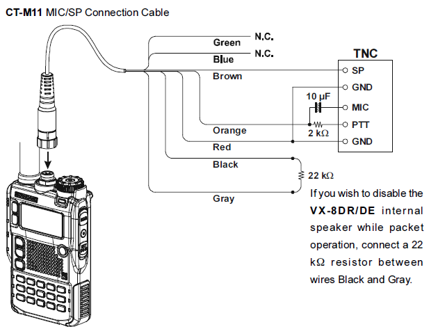
Also, based on the latest schematic you provided here is the updated connections:
Now I have soldered the connections as you suggested above and it seems to work
For testing I used the program FT8Call and transmitted a message from the Yaesu VX-8 connected to the computer with the diy cable to another HT on 144.175 MHz. After some adaption in the settings menu of the FT8Call program I could hear the distinct modem sound on the receiving HT. Hope that receiving messages on my computer will also work since I could not test that.
While transmitting I could not hear the sound on the internal speakers so the 22K resistor between Pin #7 and Pin #2 does not seem to be necessary. The funny thing is that when I am shortening ring #1 to ground aswell it gets the HT to transmit aswell when shortening ring #1 to ground. Hope that does not influence receiving?
Thanks for the confirmation. Glad to hear you got it all working.
Yes, both rings are connected to the same line: one directly, another through the resistor. The purpose of the resistor is to not shunt the the audio sent through the same line while PTT is activate.