I have a brand new ICOM M-803 a dual role transciver (MARINE SSB and HAM). This unit has been designed to use any of a PACOR modems. I have no itentions to follow this road. I want to use WINLINK, PAT, VARA together with my LINUX box.
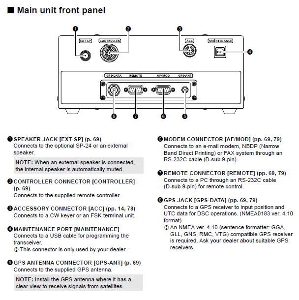
M-803 has a dedicated 9 pin serial port to connect with a computer. Its pins are as follow:
1 DCD Inputs terminal for carrier detection.
2 RXD Inputs terminal for receive data.
NMEA-OUT NMEA0183 ver 4.10 data output.
3TXD Outputs transmit data.
NMEA-IN NMEA0183 ver 4.10 data input.
4 DTR Outputs data terminal ready signal.
5 GND Connected to ground.
6 DSR Inputs terminal for a data-set-ready signal.
7 RTS Outputs request-to-send data.
8 CTS Inputs terminal for clear-to-send data.
9 NC No connection.
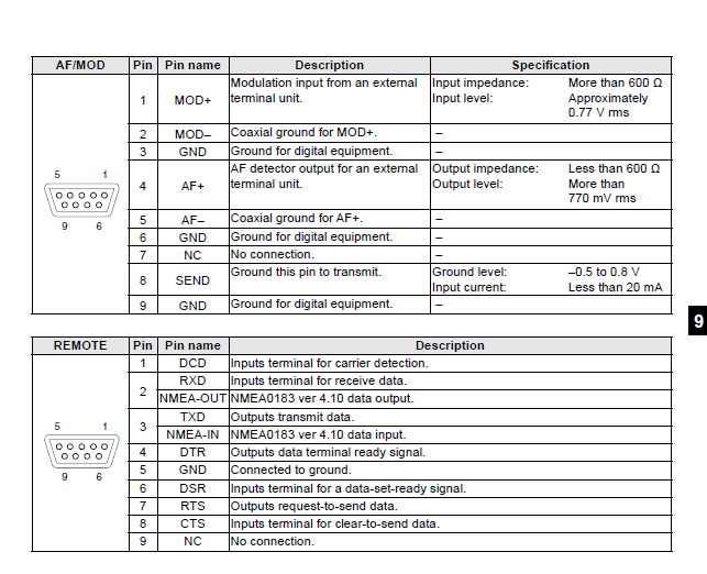
Its serial port for modem connection (PACTOR):
1 MOD+
Modulation input from an external
terminal unit.
Input impedance: More than 600 Ω
Input level: Approximately
0.77 V rms
2 MOD– Coaxial ground for MOD+. –
3 GND Ground for digital equipment. –
4 AF+
AF detector output for an external
terminal unit.
Output impedance: Less than 600 Ω
Output level: More than
770 mV rms
5 AF– Coaxial ground for AF+. –
6 GND Ground for digital equipment. –
7 NC No connection. –
8 SEND
Ground this pin to transmit. Ground level: –0.5 to 0.8 V
Input current: Less than 20 mA
9 GND Ground for digital equipment. –
REMOTE Pin Pin name Description
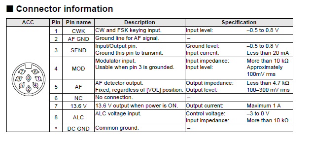
Finally, its ACC (round) ports pinout:
ACC Pin Pin name Description Specification
1 CWK CW and FSK keying input. Input level: –0.5 to 0.8 V
2 AF GND Ground line for AF signal. –
3 SEND
Input/Output pin.
Ground this pin to transmit.
Ground level: –0.5 to 0.8 V
Input current: Less than 20 mA
4 MOD
Modulator input.
Usable when pin 3 is grounded.
Input impedance: More than 10 kΩ
Input level: Approximately
100mV rms
5 AF
AF detector output.
Fixed, regardless of [VOL] position.
Output impedance: Less than 4.7 kΩ
Output level: 100–300 mV rms
6 NC No connection. –
7 13.6 V 13.6 V output when power is ON. Output current: Maximum 1 A
8 ALC
ALC voltage input. Control voltage: –3 to 0 V
Input impedance: More than 10 kΩ
Is it possible to create a set of cables to control this radio?
Hi, I am impressed with the speed you responded. This is very quick indeed.
Now, I have another question - how much will this cost digirig + the Serial CAT + ACC cables?
Mark,
I’d recommend you try building the cable at home or with somebody at your local club.
You can also check with https://hammadeparts.com/ if you prefer to outsource this project.
building cables is OK but I have no idea what end connectors to use where. I assume one cable with have DB9 male and the other will have the round ACC 8 pins but what on the other end of each cable and how one end relates to the other? could you provide a diagram or a sketch?
Re. parts: for prototyping and small scale build I source the components from Amazon/eBay/Aliexpress. For the cable build I typically start with the cable that already has a correct connector on one side. You can look for DB9 cable that has all needed pins wired or TRRS cable.
Re. Digirig configuration: The serial connection being DB9 and using the standard RS-232 pinout I would go with RS-232 configuration for this radio
Mark, I also have an M803 and I am looking at the DigiRig and the Digirig Lite for the radio. I currently have a Pactor but want to switch to using VARA HF. How well did it work for you? Did you make your own cable or find someone to make it?
Thank you,
Harley Soltes
KK7HMS
Thank you for the tip on the IC-736 cable. Since I am not a homebrew tech, what are the options for getting a cable made up for me? I would like frequency control from Vara/Winlink. My GPS signal for the radio is also acquired from the laptop, so I am trying to replicate as much of the Pactor modem connection features between computer and radio as possible.
I wonder if there is any chance to use the Pactor cables adapted to the Digirig plugs for that serial connection? I will be disconnecting the Pactor cables to connect the sound card for VARA use to the ICOM M802 control box.
Yes, you can make a set of cables to control the ICOM M-803 using the pinouts you’ve shared. Since you’re planning to run it with your Linux setup using Winlink, PAT, and VARA, you’ll mostly work with the serial and ACC ports. For a stable connection, it’s a good idea to use proper marine control cables that are shielded and suited for the marine environment. These cables can be custom-made or you can buy them from marine electronics suppliers. Just make sure each wire lines up with the right pin function like audio input and output, push-to-talk, and data transfer. Also double-check voltage levels and grounding to keep the radio safe during use.