Hello everyone.
Someone gave me a YAESU FTM-3100E.
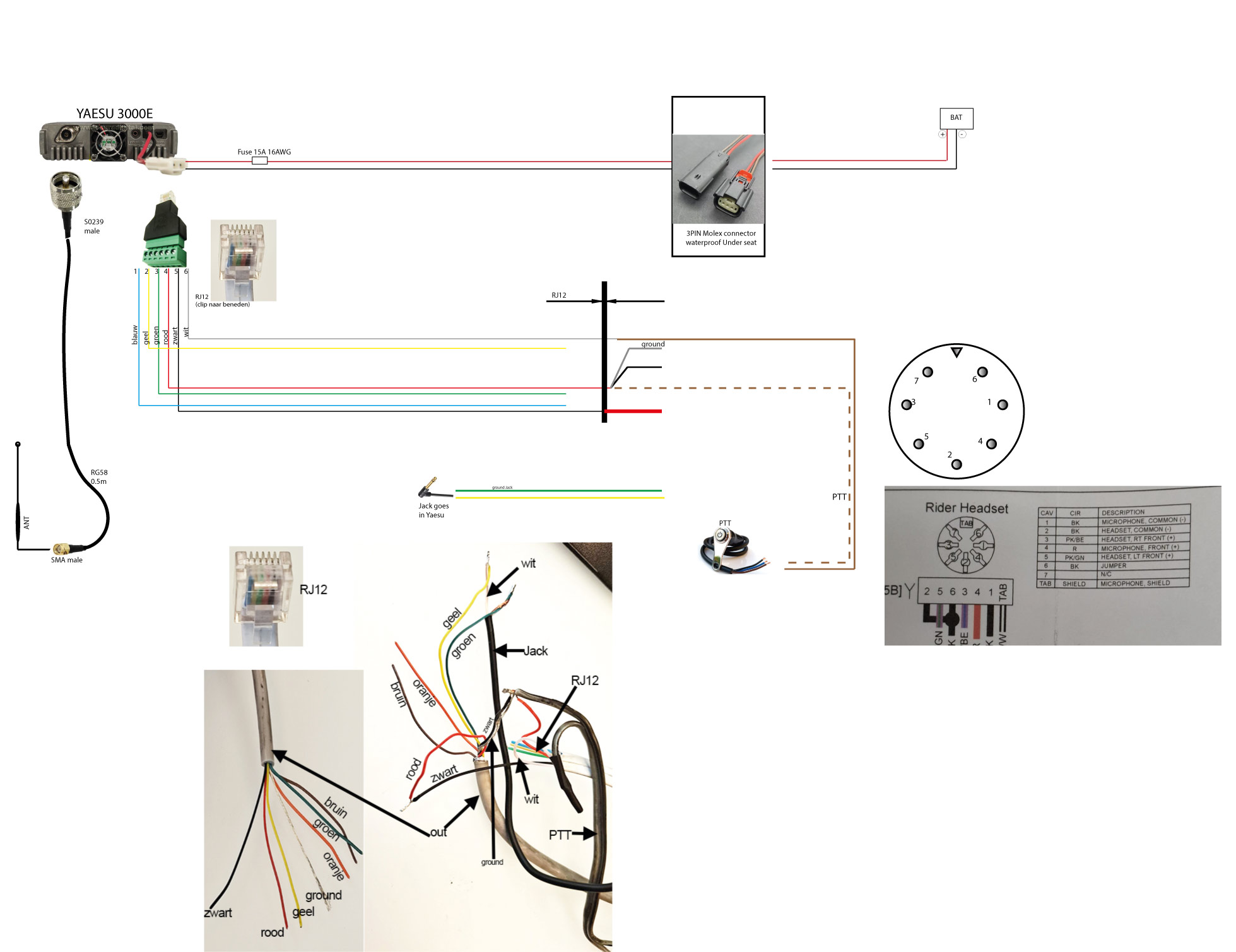
I want to use it on my motorcycle, so with a headset (which is connected with a DIN7 cable, coming from the RJ12 connector).
The cable coming from the R12 connector is connected to the DIN7 cable.
This one has been cut. The DIN7 connector itself is gone.
So I can visually see the connections that were made; here and there, a few wires are soldered together. So these must be correct since the Yaesu has been used on another motorcycle.
A diagram is attached.
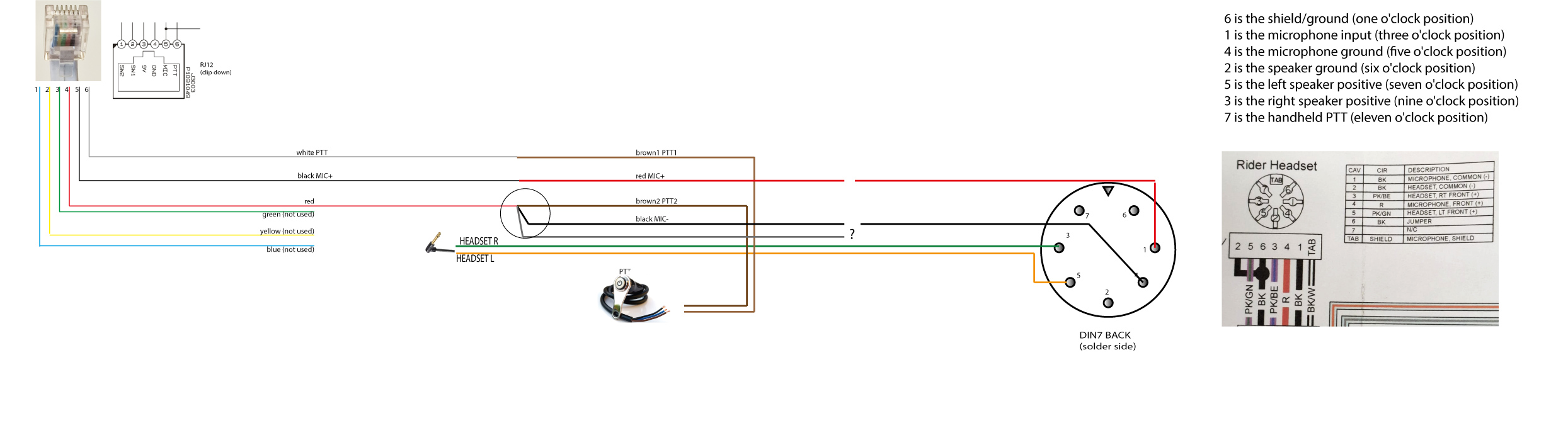
I also found the pinout for the DIN7 connector in a workshop manual. However, I don’t understand it.
Can someone help me and tell me which wire goes on which pin, or how exactly I should solder everything together?
The PTT button is separate from the DIN7.
The color coding out of cable labeled “out” doesn’t match the rider headset chart so it’s hard to confirm the wiring. Check the connections between DIN7 and actual color wires and I’ll take another look at it.
I would expect to see lines HEADSET RT (3) and HEADSET LT (5) connected together since you are getting mono signal out of the radio and send it to both sides of the headphones, but I don’t see any two wires twisted together.
Hello,
Thanks for your reply.
I’ll check everything again this weekend and make a note of it so everything is correct and clear.
Indeed, I also noticed that there’s only one output for the headset. But this might be because it’s connected to the connector itself (which I no longer have).
More later… and thanks again.
Here’s an update.
I did a lot of testing this weekend.
Ultimately, the headset microphone turned out to be defective.
It works fine with a different headset.
In my schematic, you can see the cable coming from the transmitter on the left side.
This is soldered to another cable that should hold the headset connector.
I got the soldered cable like this; the connector for the headset was cut off.
The jack is a mono jack, but with this connection, I get sound in both earphones.
The PTT button works.
The microphone connects to the black and red wires from the transmitter, Mic- and Mic+ respectively. A ground cable is also soldered to the MIC-. This is the only one I don’t know where to connect. It’s probably just for interference reduction.
On the right, you see the connections I found online. The colors don’t match, but the numbering does, and apparently, it’s correct.
So, only the ground cable remains…
I’d connect MIC from the radio to MICROPHONE (+) instead of MICROPHONE (-)
It looks like in the pasted picture of the connector all black (BK) wires are ground/common connections.