For your techno-neardry pleasure, Barry K3EUI shares the results of his deep dive into FM deviation using Digirig:
Question:
Can a Digirig Mobile V1.9 produce enough TX audio to drive an Icom 2820 set to 9600 baud to “full” deviation (3.6 kHz) on 2m?
I now have a Digirg Mobile V1.9 from K0TX and it is hooked up to an Icom 2820 via the typical 6 pin MINI DIN AUDIO cable.
PTT is via a (dumb) COM port, using the RTS pin to ground the PTT pin 3 on the audio cable to the radio.
All very typical.
I did not use any kind of serial port COM cable. The Icom 2820 does not have CAT.
The Digirig does have a USB to the Win10 computer for audio and one COM port.
Question: with the Icom 2820 rig set to 9600 baud (MENU) for wide-band modes, can the Digirig drive the radio to a 3.6 kHz deviation?
Answer: YES
Here is the evidence.
I set up the Windows 10 TX audio in PLAYBACK (SPEAKERS) Digirig sound card to 0 dB attenuation (max output)
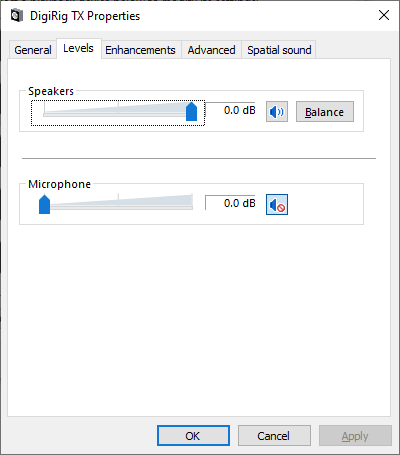
There is no TX level knob or TX level potentiometer inside the Digirig (saves space and money) to vary the TX modulation levels.
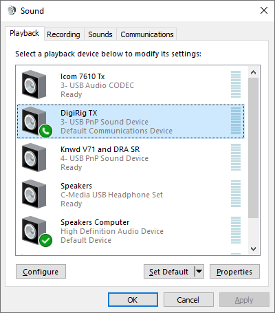
I started FLDIGI and picked the Digirig sound card, PTT via COM port.
I started up my SDRplay (hardware) and RSP Spectrum (app by Andrews) to map out RF waveforms
I set the Icom 2820’s VFO to 145.690 MHz. No PL tone. 5W LOW power.
I set the SDRplay and RSP app to receive on 145.690 MHz with a 20 kHz bandwidth.
The resolution “bandwidth” is about 15 Hz (fine enough to see details) set in the app under FFT

I set the FLDIGI TX “attenuation level” to a value of 5.5 (it says -5.5) dB and pressed the TUNE button.
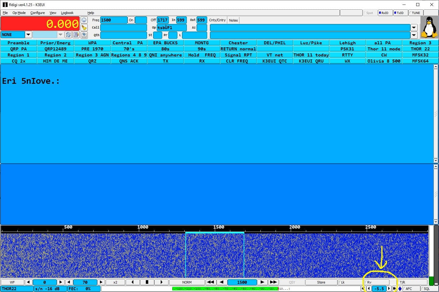
Thus the TX audio is a single-pitch sine wave of 1500 Hz into the Icom 2820 (set to 9600 baud) via the Digirig sound card.
I can use the FLDIGI TX “attenuation” setting to alter the amplitude of the TX audio - keeping the pitch constant at 1500 Hz.
Now we watch the RF Spectrum on 145.690 MHz with the RSP app.
Here is the spectrum with NO modulation, but VFO set to 145.690 MHz.
You can “see” the RF carrier at 145.690 MHz
I’ve heard this called a “dead carrier” meaning NO AUDIO.
With very slight modulation, the carrier amplitude starts to drop and the amplitude of the sidebands start to increase (that’s the way FM works)
You can start to hear this single pitch tone on a second receiver.
Interestingly the TOTAL POWER output of the radio does not change with levels of modulation (unlike AM and SSB).

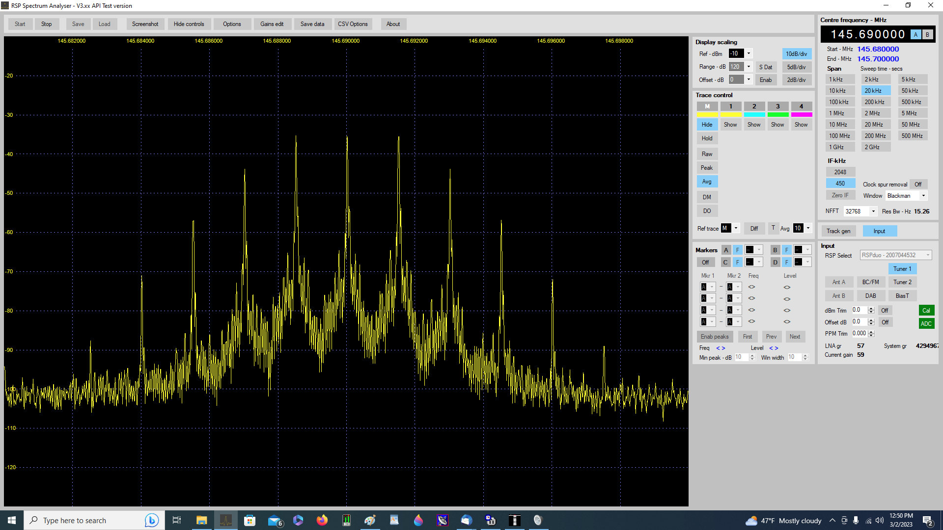
Next, you can see the modulation level where the CARRIER amplitude has dropped to the same amplitude as the first sideband pair.
So kind of strange if you’ve never seen an FM spectrum of a single-pitch sine wave.
One tone in (1500 Hz) results in multiple sidebands, each spaced +/- 1500 Hz from the RF (original) carrier at 145.690 MHz
The whole spectrum shown is 20 kHz on this view.
This picture shows what is called a MODULATION INDEX value of about 1.5
Keep increasing the TX audio amplitude (keep the frequency or pitch constant) and what happens?
If you were to listen on a second receiver, the sound gets louder, of course. The pitch does not change.
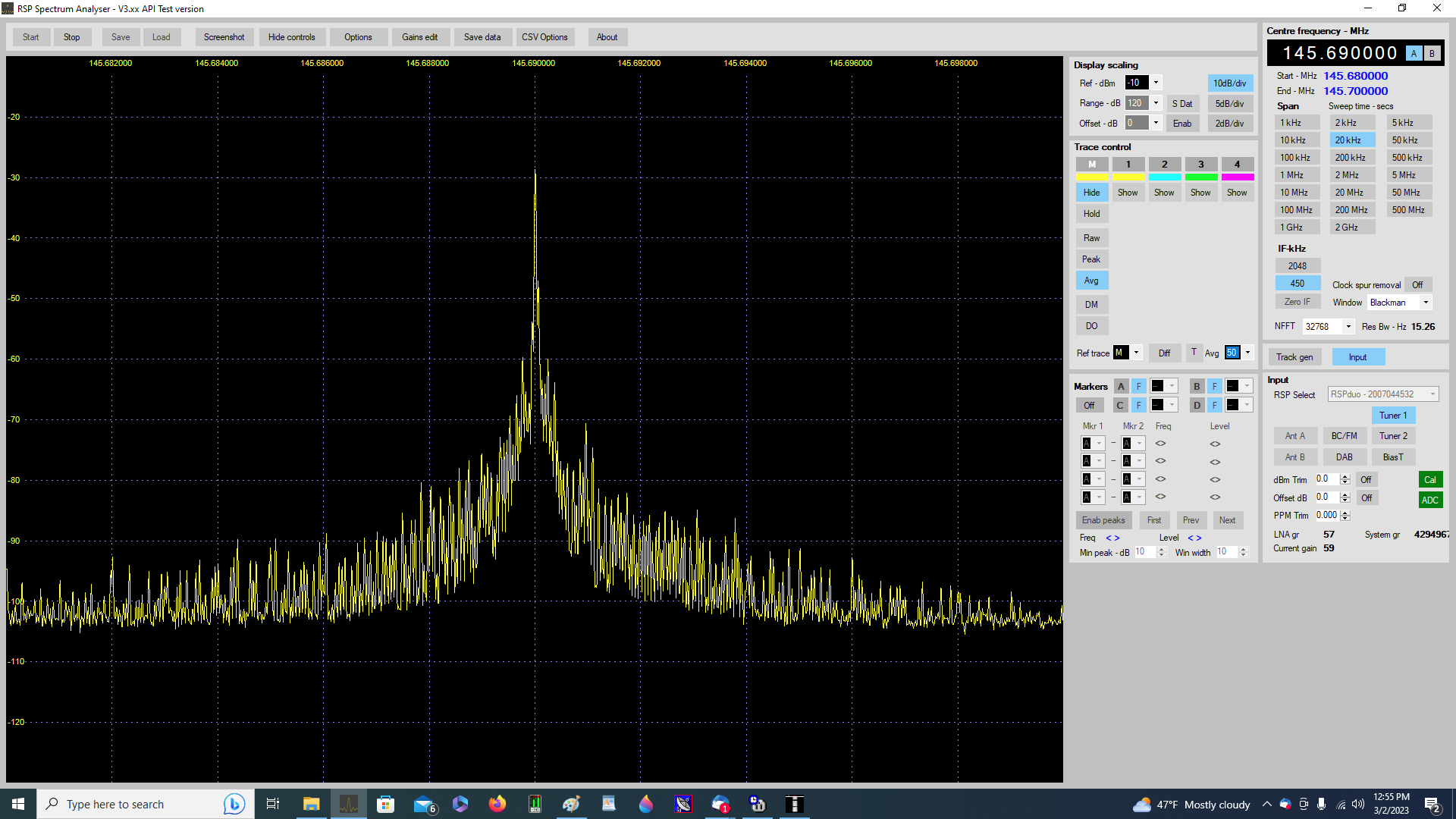
When the carrier shows a “null” the modulation index has a value of about 2.4 (two digit precision).
You can verify this by modelling the RF spectrum by the Bessel Function (too much math but see ARRL Handbook on FM modulation)
This means that the product of the MODULATION INDEX (a pure number) and the AUDIO PITCH (khz) is the DEVIATION
So the deviation of the 145.690 MHz RF signal produced by this Icom 2820 at 145.690 MHz is
DEVIATION = 2.4 (1.5 kHz) = 3.6 kHz

So the Digirig is capable of full deviation of this Icom 2820 when set up for 9600 baud (wide bandwidth) modes like VARA FM wide.
The next plan is to repeat this at a variety of audio frequencies: 300 Hz out to 1500 Hz in 100 Hz steps.
Since the radio is set to TX at 9600 baud, I know the deviation does NOT depend on the audio frequency.
The deviation DOES depend on the “amplitude of the audio”. How can we test that?
Thus, changing the audio frequency by FLDIGI, but keeping the MODULATION INDEX constant (by making the carrier null) will tell me the DEVIATION.
Deviation = MOD INDEX (2.4) multiplied by the audio pitch (kHz)
This is sort of like having a very inexpensive ($100) DEVIATION METER using the RSP Spectrum software and a SDR hardware.
We will then look at Deviation (Y) vs. FLDIGI TX level attenuation (X axis) and see what kind of graph we get.
There has been some discussion on the various IO groups about the “opimum” modulation audio for modes like VARA FM and FLDIGI on FM.
It does not matter whether on simplex, or when sent over an FM digipeater or even an FM (analog) voice repeater (with the owner’s permission of course)
Too little audio and the S/N suffers.
Too much audio leads to distortion and again, the S/N suffers.
This might lead to some conclusions about how to set up audio levels on the FM modes on VHF/UHF.
de k3eui Barry
West Chester PA
March 02 2023