I am having issues setting up the TS-480SAT with the digirig as I am not receiving audio into my computer from the radio. I have purchased the RS232 version 1.9 last fall and had issues getting it going. I put it away and got it back out recently to see if I could get it working again and I’m still stumped. I’ve read forums, watched videos and I can’t seem to get it working.
Are there any special menu settings in the TS-480 that I should know about in addition?
I have done modes with the signalink and have messed with direwolf tnc to get numerous radios up and running digital so I understand how to do it.
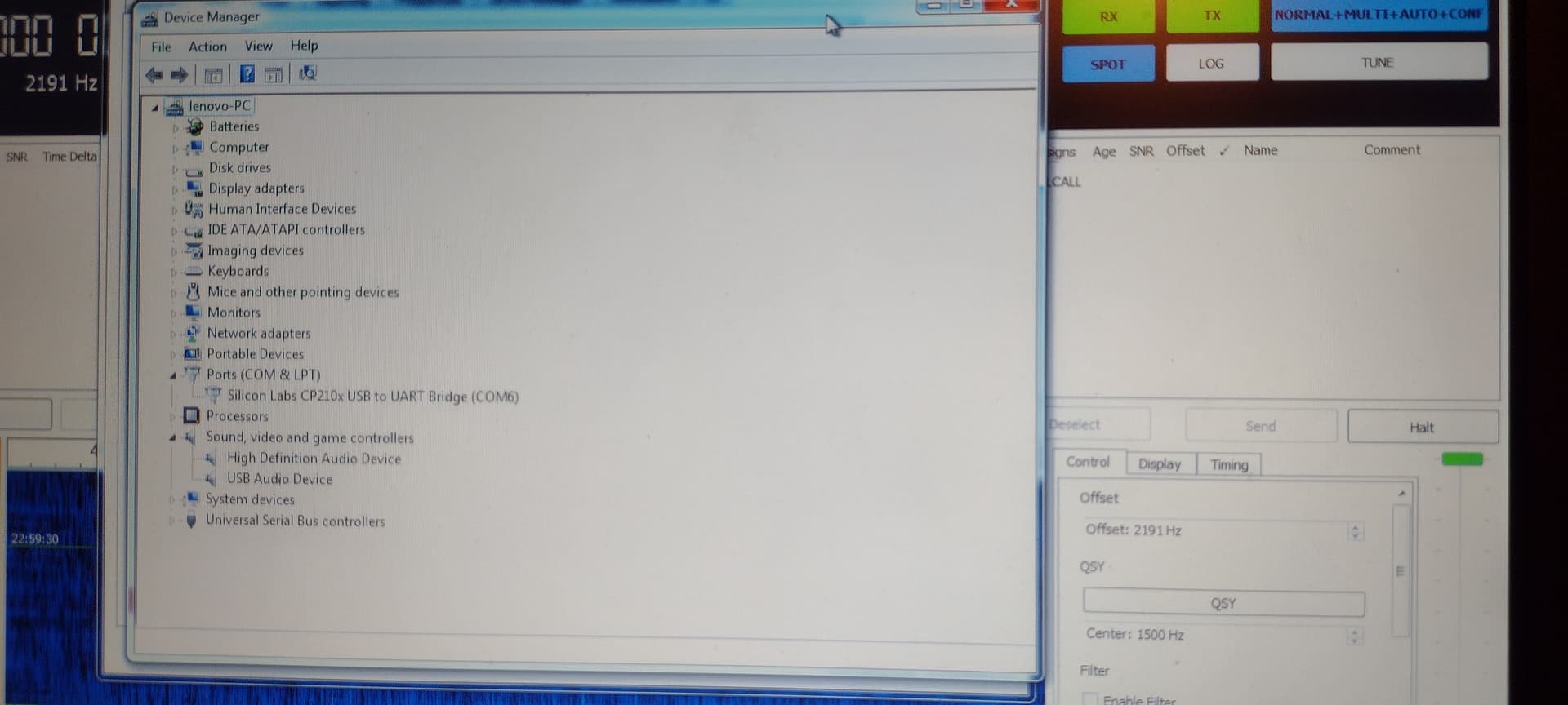
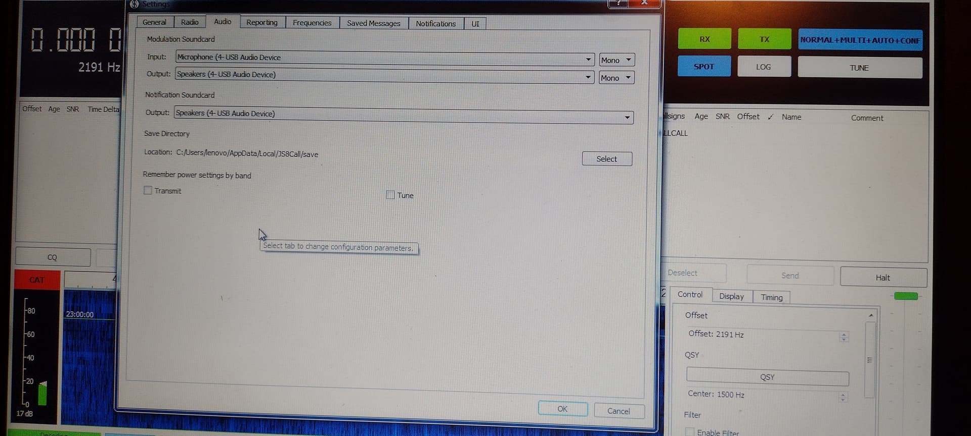
The audio codec is showing up correctly in my device manager and the proper one is selected in my menu options. I am running JS8 Call but no audio is coming in to the radio.
I will say that I made my own cables ( I know the default response is going to be that I made them incorrectly. I have checked and rechecked the connections based on the schematic given for the cables on this site) and while there could possibly be an error I would like to at least try to figure out what is happening as purchasing a set of cables may give me the same results.
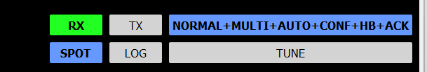
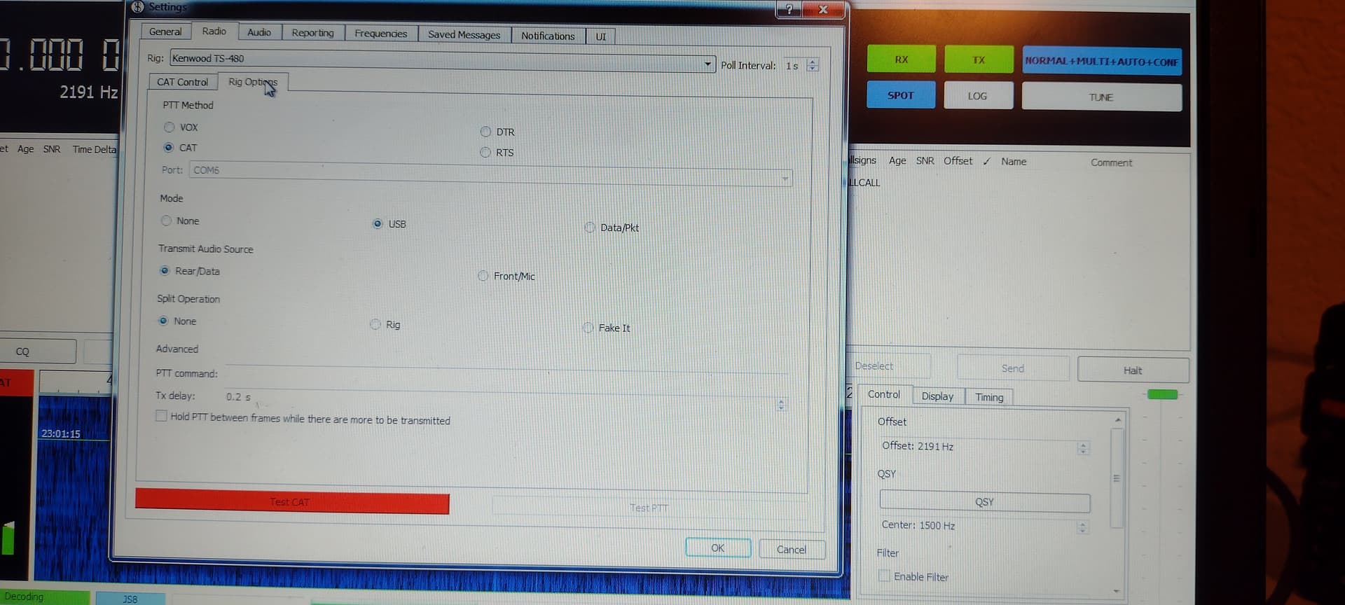
That’s frustrating. I don’t have your radio, but I operate JS8CAll regularly. Is anything else working? VFO Frequency selection? PTT Test? CAT Test? Audio out? There is a setting in JS8Call Operator window:
So JS8 will say that receive is working, however, the program isn’t registering any volume adjustment from the radio…which tells me the radio audio isn’t getting in. It’s also not the computer mic audio either because it’s not detecting any sounds I make moving around.
Like I said…I’m unsure if it’s my cable, my settings, or a menu item I’m missing on the radio.
When a user thinks everything is OK, but it’s not working, many users here go ahead and post a screenshot of the configuration window for their application or a photo of the corresponding menu item set on the radio. Sometimes another set of eyes on a problem will uncover a way forward. When I am having difficulty, I reseat the physical connectors, too.
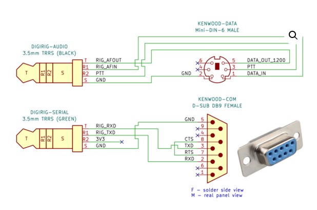
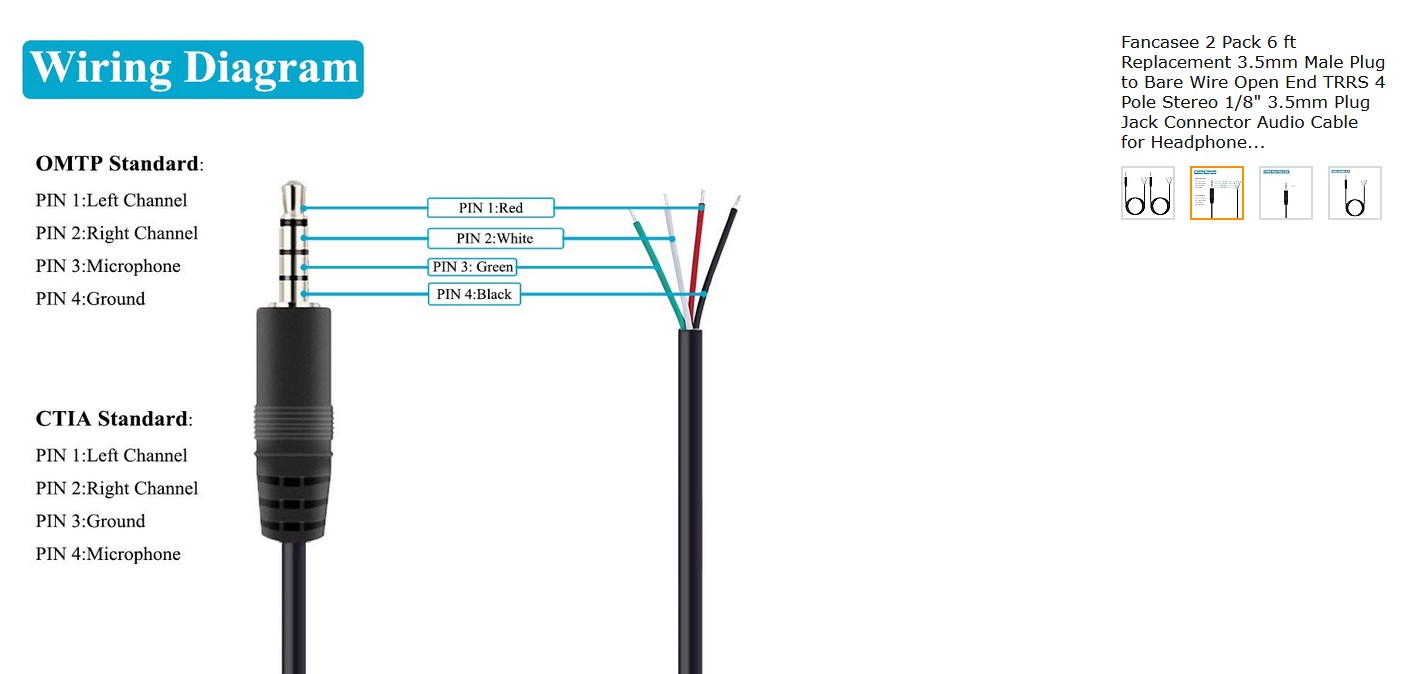
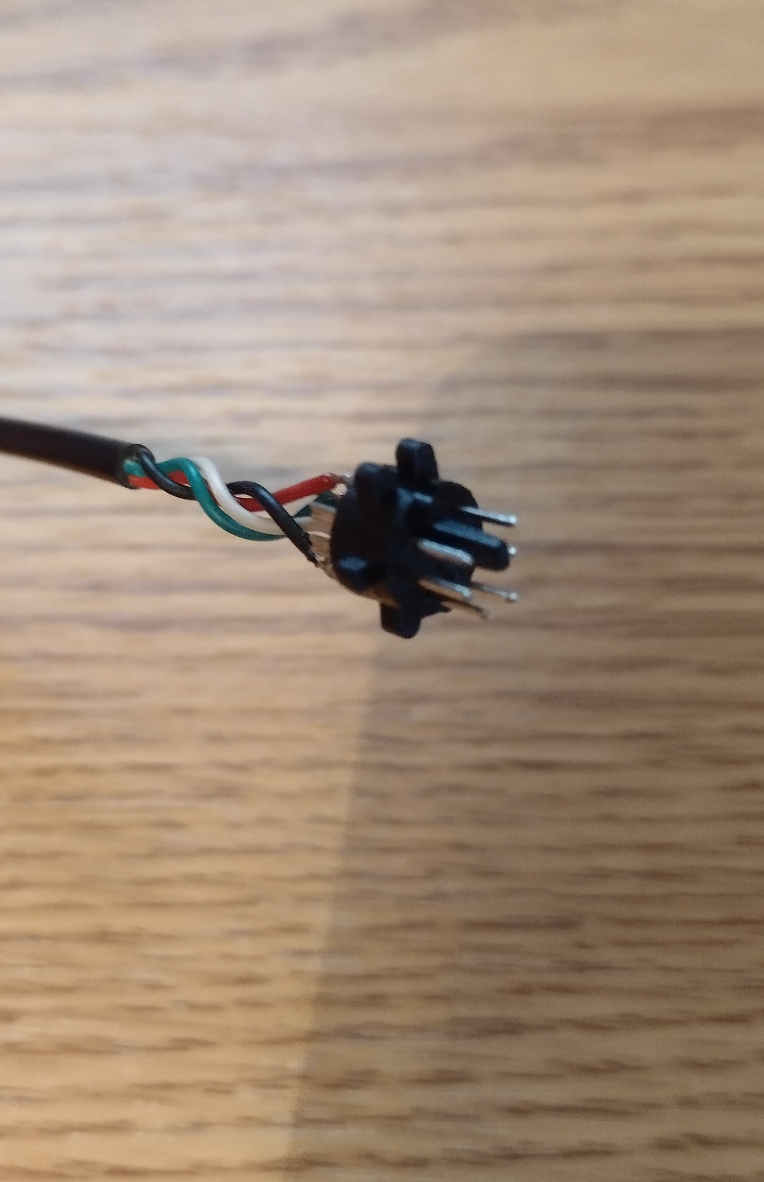
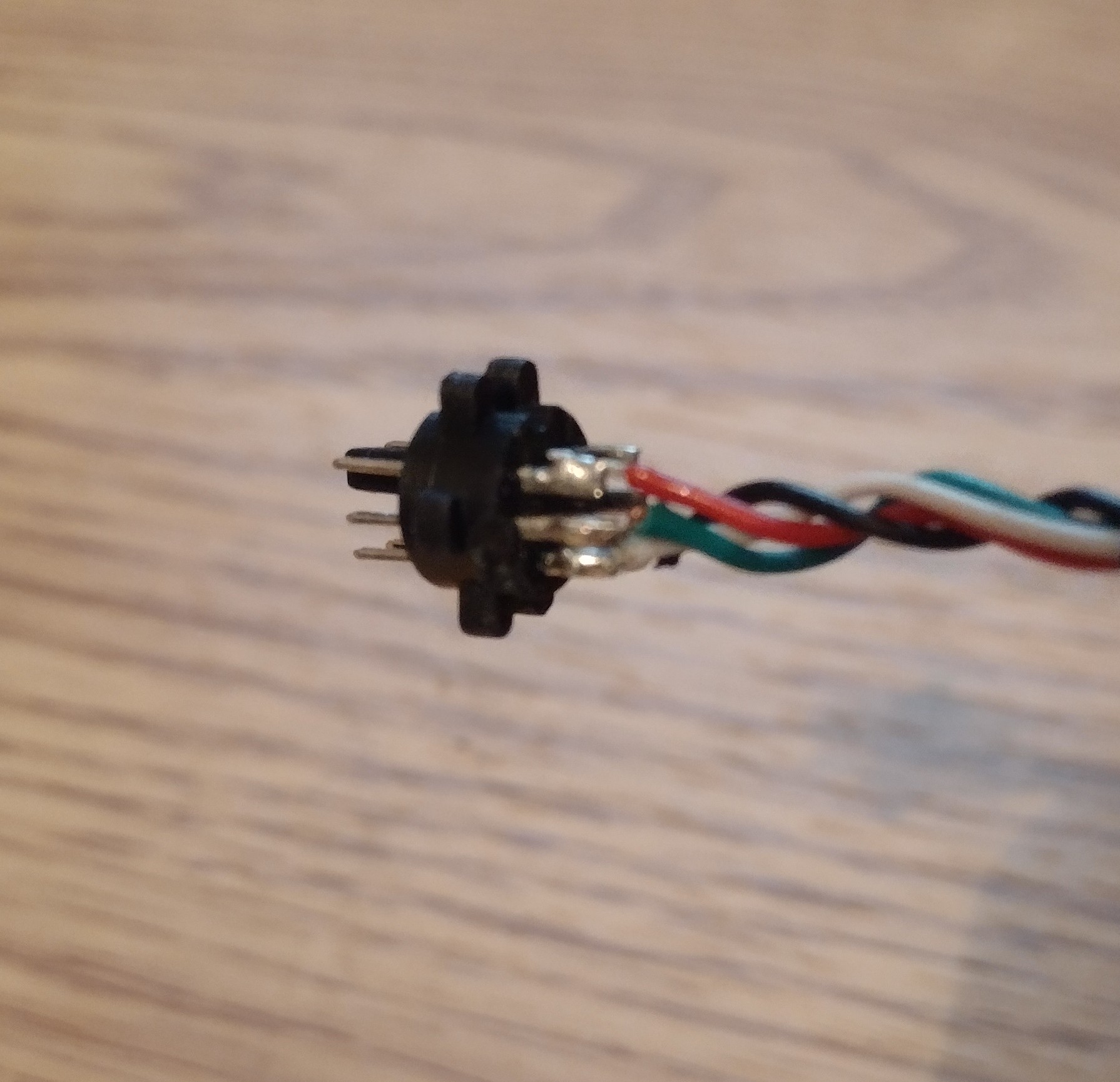
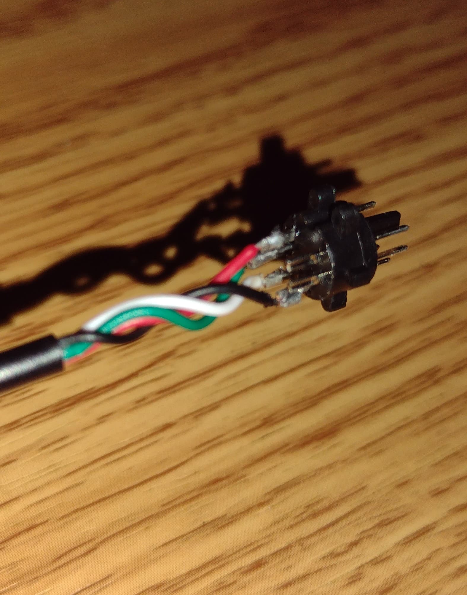
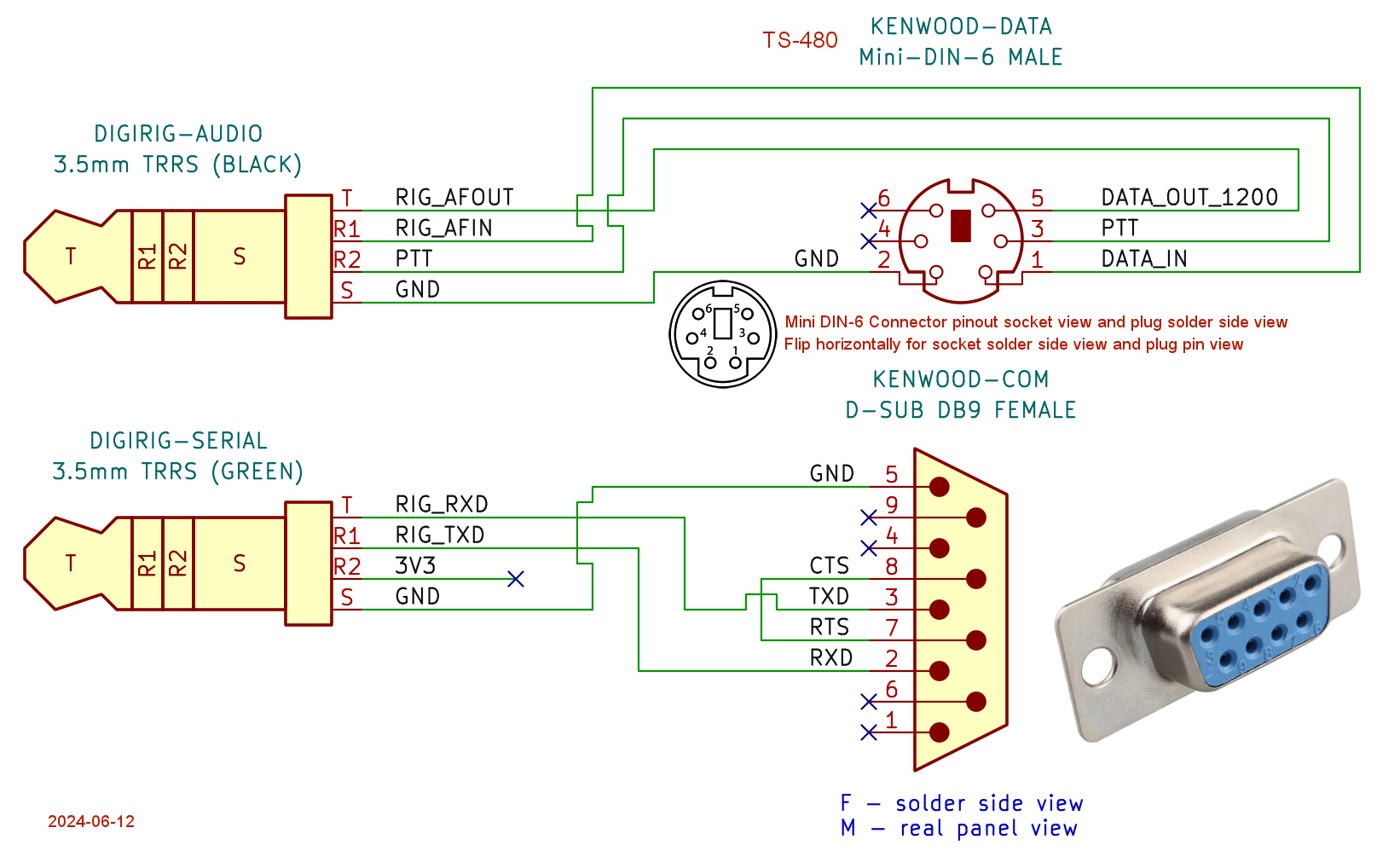
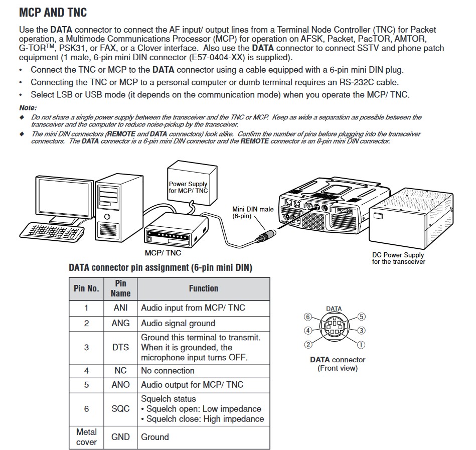
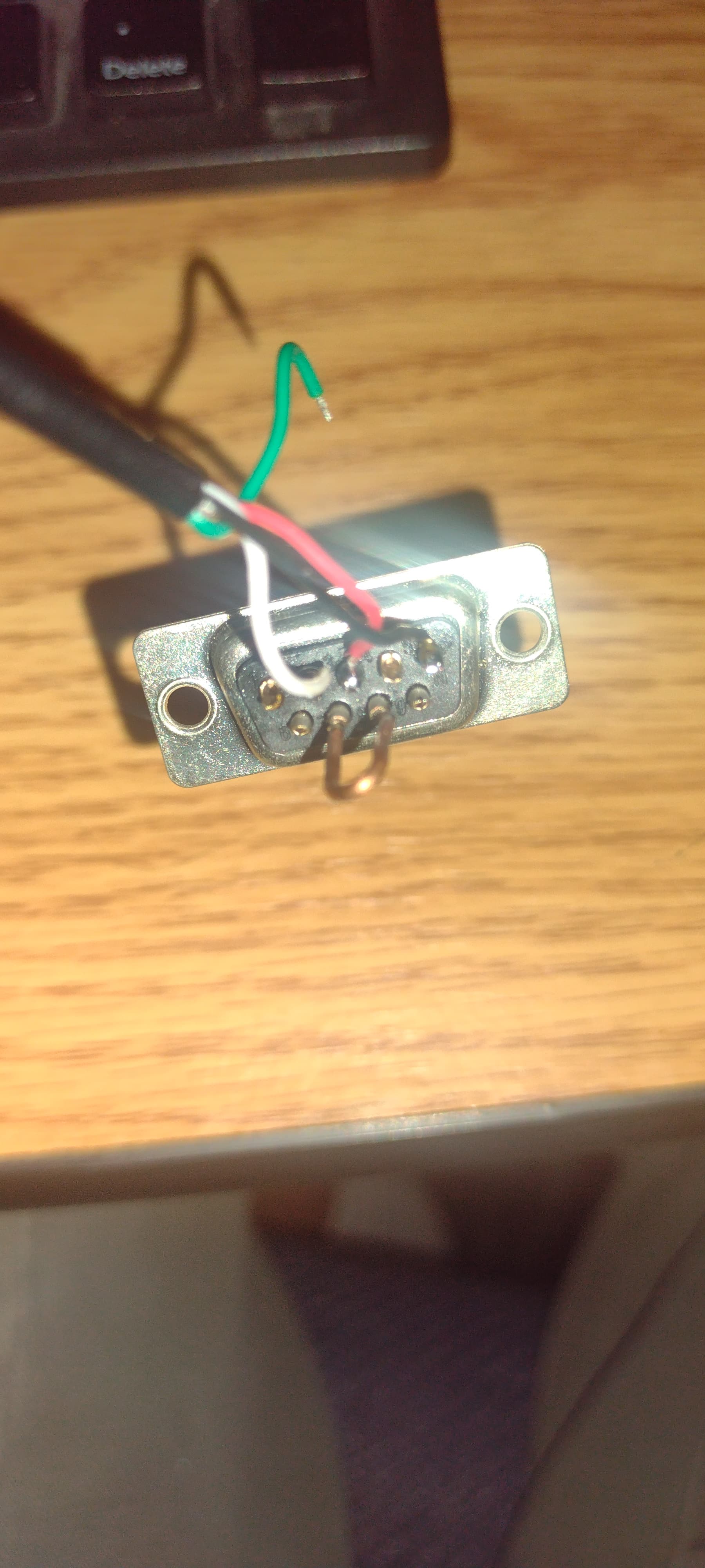
I thought this information might help as reference. I went ahead an took apart the cable I made to double check any errors. I’ll post the following digirig cable pinout guide and then the cable I purchased from Amazon. I will then post pictures of the cable I made setting in the same position as the diagram for reference.
So, a couple things. I tried to take all these pictures from different angles with the cable point in the same direction with the pins out facing up just like the view from the diagram. I made the assumption that when viewing the diagram I was viewing the pins facing out although it’s not labeled which way it’s facing. Judging by the black square I’d assume it’s facing out.
The other thing I just noticed is the wiring diagram has two different pin outs depending on what standard of audio is being used. Now…that I don’t know. I might have to switch a few wires around and see if we can’t find any other solution.
Twas a little difficult to solder so…that will be my last resort.
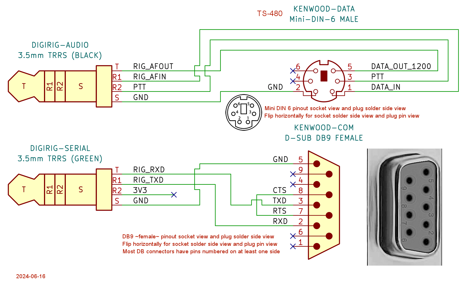
I had some confusion in the early days. I thought that the pins were labeled on the digirig site incorrectly, and exchanged emails about it. In the process, I created new images for my digirig cables that make sense to me.
I opine that the web site should have only one view, and that is the rear of the DIN plug, AND it should be correctly labeled for that view. (After all, this has naught to do w the ~panel~; it’s all about the TRRS and the DIN plug.) I checked my TS-480 DIN cable to make sure that it agrees with what I posted.
The web image has “M - real panel view”, which I suspect is “rear panel view”, for the DB9. Again here, I think it should ref only one view, (I choose solder side) and that should be clearly stated. Images should use standard “socket” and “plug” nomenclature.
My HF antenna is down for the count, so have never used the TS-480 DIN 6. I verified my V71 cables worked correctly. I didna confirm the TS-480 DB9 schematic.
Glad you are making sense and apologies for any possible confusion.
The pinout is the same for the cable connector’s solder side view and radio’s outside socket view.
F and M stand for female and male connectors which should give additional clue as to what is being discussed.
I don’t mean to be rude…you have been quite helpful, after all…but this is exactly the point I tried to make months ago when I was trying to verify that a “Yaesu” cable would connect to my Kenwood.
The cable is sold as assembled, so my assumption…and it seems the assumption of the OP, too…is that the pinout diagram refers to the only thing I can reach…the DIN ~plug~ ~pins~. But that’s just not correct. The diagram actually shows the solder side of the plug, so we all need to mentally flip those pin assignments when we measure. You can see that I have provided a clear diagram and statement for my image.
If I understand the OP images correctly, that DIN plug is wired in the ~incorrect~ mirror image, perhaps because (s)he made the same interpretation of the digirig image that I made…that it refers to the pin side. So to be useful, every cable schematic…and they are ~most~ USEFUL, should be much more clearly labeled. Feel free to copy what I did. I looked at the image of the TRRS pinout from the OP, mentally traced the lines on ~my~ image, and came to the conclusion that the OP has wired the connector in reverse. YMMV. I might be wrong
I don’t understand “M - real panel view”. Compared to the imaginary one? I’m a physicist, so I get that…
So based on what you are saying, need to switch to the opposite side all of my wires? You should be able to determine my interpretation of the plug picture. What I determined was that I was looking at the plug pins as if the casing was still on the plug and that the labels were the same pins on the solder side.
I’m guessing now they need to be switched around. I tried flipping the audio receive and ground pins to see if I could see any of the waterfalls on JS8. (No good, but then again I couldn’t mess with it much for the next few days.)
Who knows it might help have a slightly tilted 3d labeled diagram on something like this.
Is there any way you could label down your digital settings on the TS-480?
I also looked at the TRRS image with the red-green-white-black wires labeled.
I used the diagram I posted to trace each TRRS line to the plug, keeping track of wire color, and assuming the plug connection is from the wire side. That resulted in (for ~this~ cable) red-green-white running down the R side of the plug solder side. I saw your image has them on the left, so I opined that you followed them correctly, but viewed the digirig image as being from the plug pin side, not the plug solder side. All you have to do is swap all 4 wires horizontally
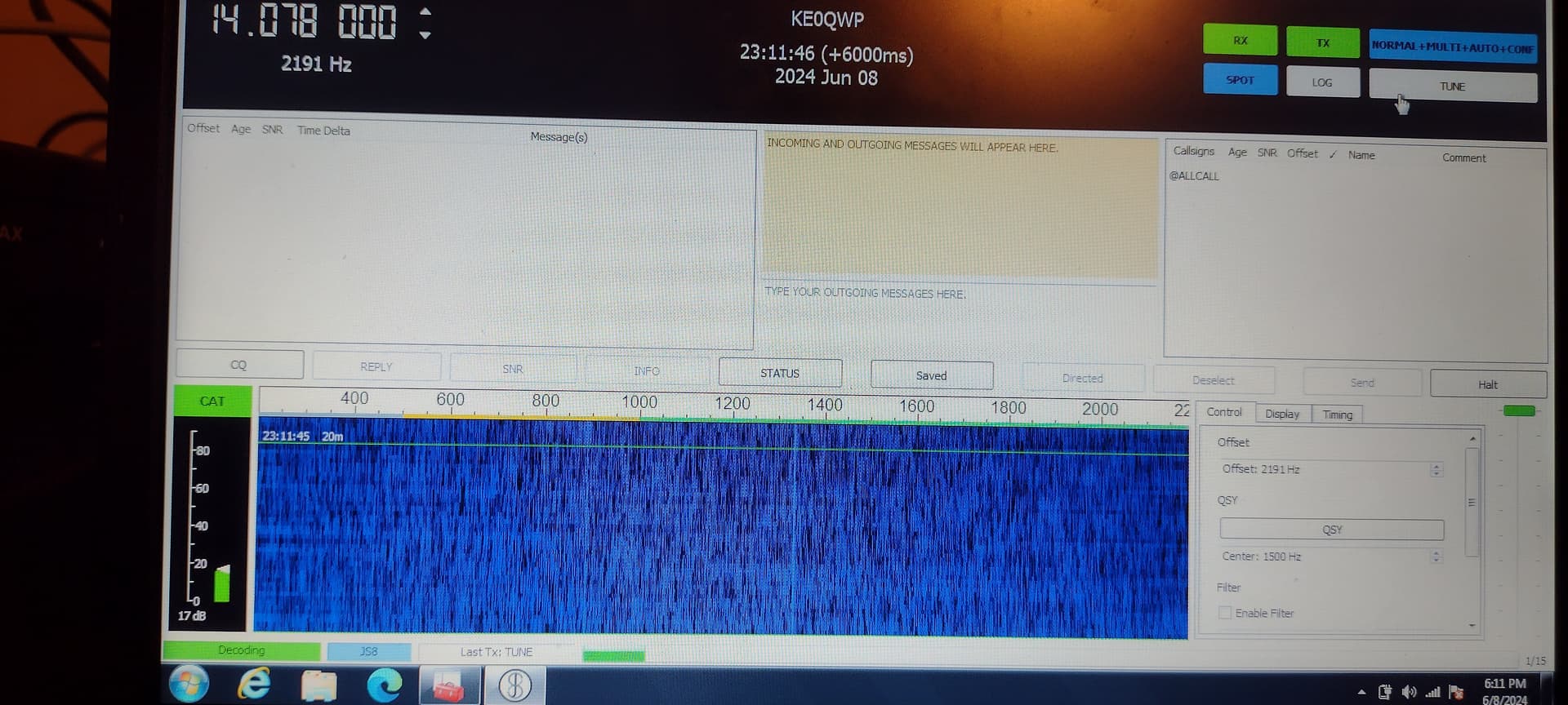
Update: So I switched the pins around and audio does work finally! I had to go into menu 47 on the Kenwood and lower the AF Output into the computer. The audio is receiving just fine now.
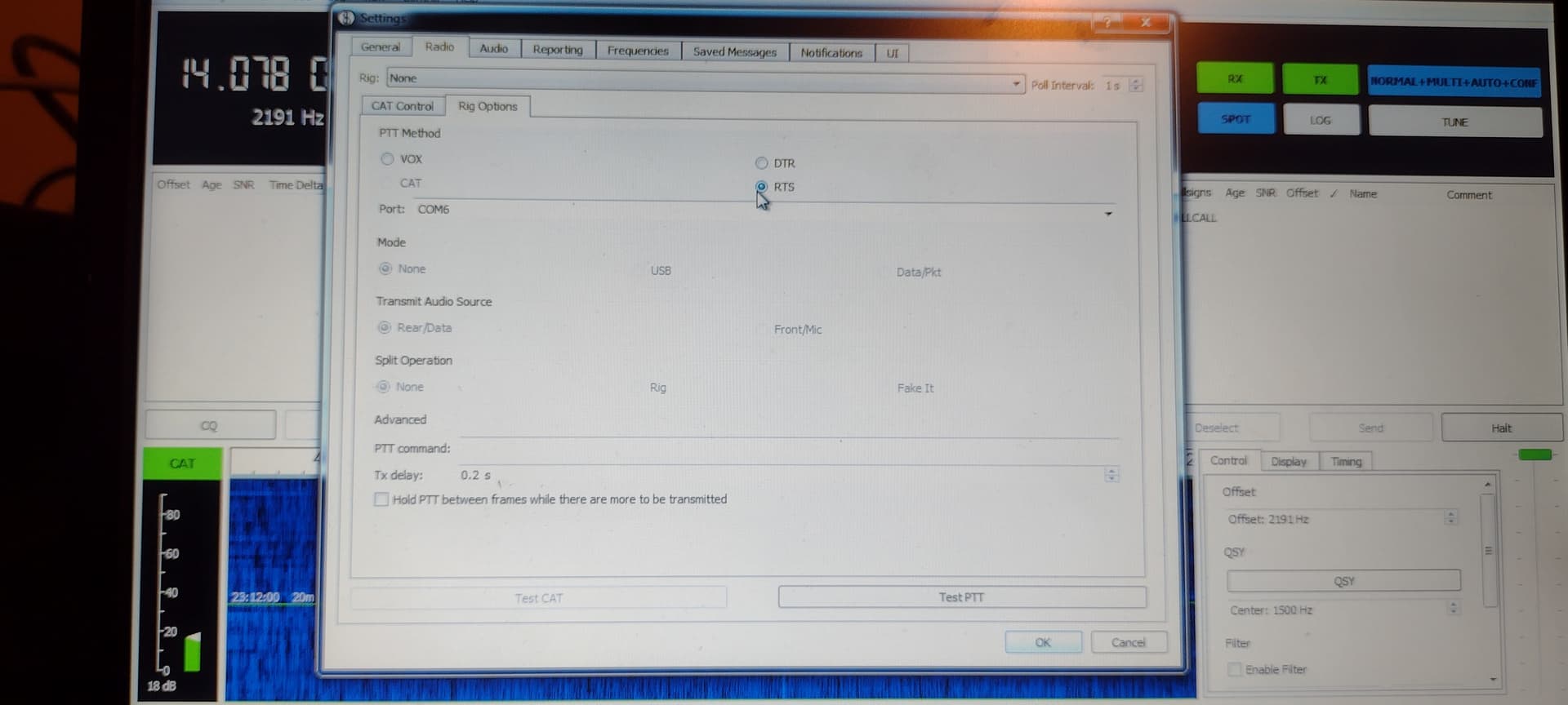
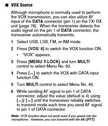
However! … I have not been successful in getting the cat control to work. So I have included the following pictures in this post from the manual showing any future users how to use VOX if they might be having issues with CAT control. The following set-up is working with JS8 call.
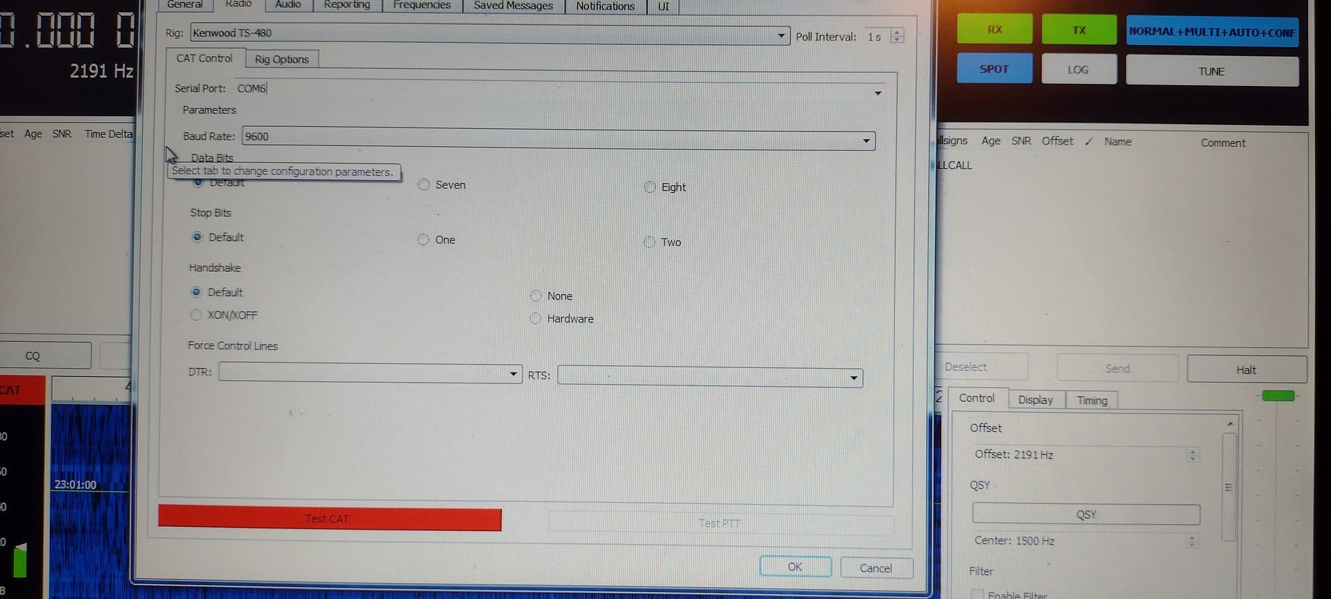
I have double checked my DB9 connector and I have soldered the pins correctly as shown in the diagram. I could use some help on getting the settings correct in the radio and software. I feel like I’ve used every single configuration I can possibly think of and nothing is working. I will include some helpful information in this post from the manual.
I can tell that my radio is receiving data from the program because the like “PC” icon show up on the radio screen as CAT control is trying to communicate with the radio.
I have also made sure the CAT control information listed in the manual is set on the radio and in the program.
The DB9 looks wired correctly. Note pin numbers on the part on the back, so it’s easy to get it right. The nice thing about the DB connectors is that if you are supposed to jump, say, pins 7 and 8, there is no ambiguity; you’d jump the same pins on either the male or the female connector. It’s just that the solder side of them are mirror images, but still with no ambiguity.