Good morning.
Bringing this older thread back to life. I am having similar issues as the OP.
I am however using Vara AC and Vara HF.
I have no CAT control but it “seems” that PTT works.
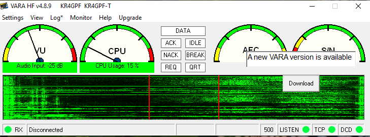
Our local ARES group is doing weekly check-ins on VARA now. I bought a Digirig off Amazon and the cables for the TS-480 at Gigaparts. I have tried multiple settings on VARA, the computer and the radio, but none seem to change anything. My Emergency Coordinator was able to see my beacons and my CQ calls but it would not connect on his end. I too see others beacons and CQ calls and I am unable to connect. I do hear audio through my radio and the Vara waterfall shows signals.
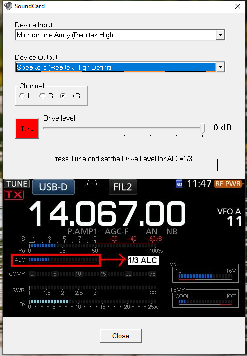
On radio, I do have VOX turned on and menu 60 “vox on with data input” turned on.
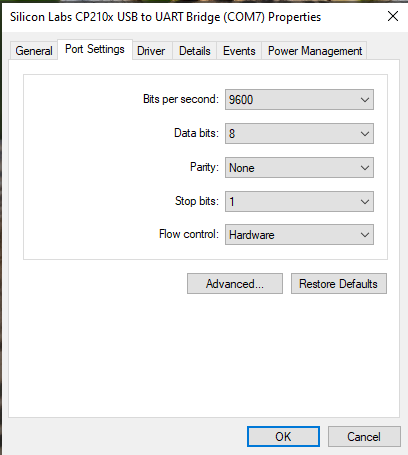
Baud rate matches computer, and vara.
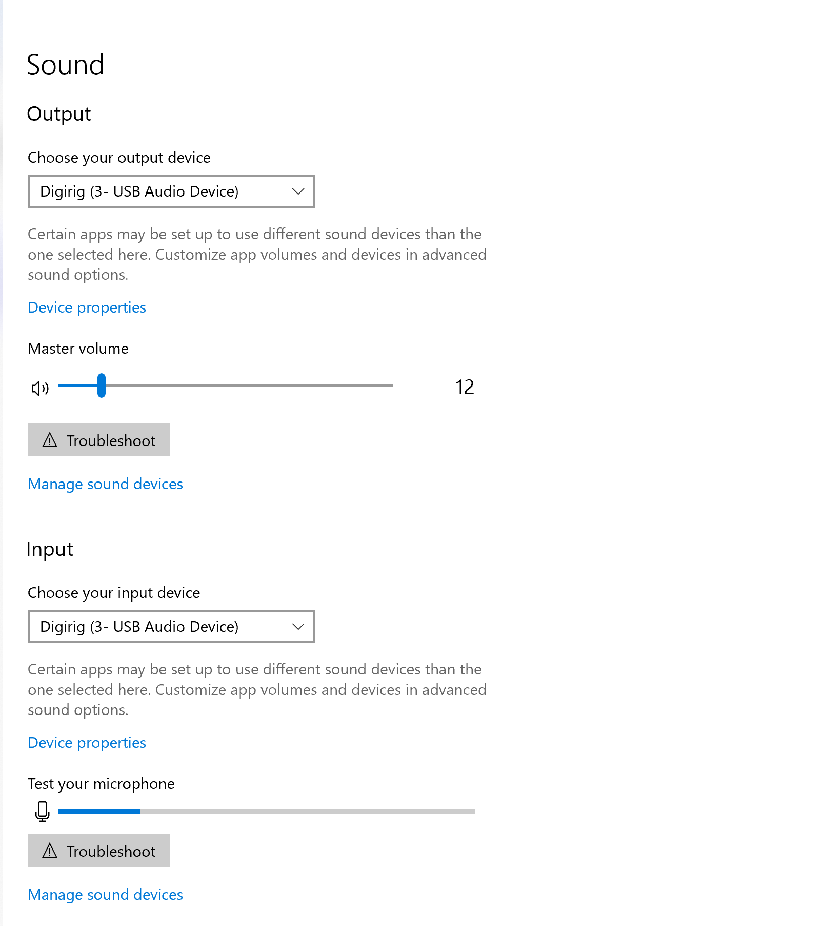
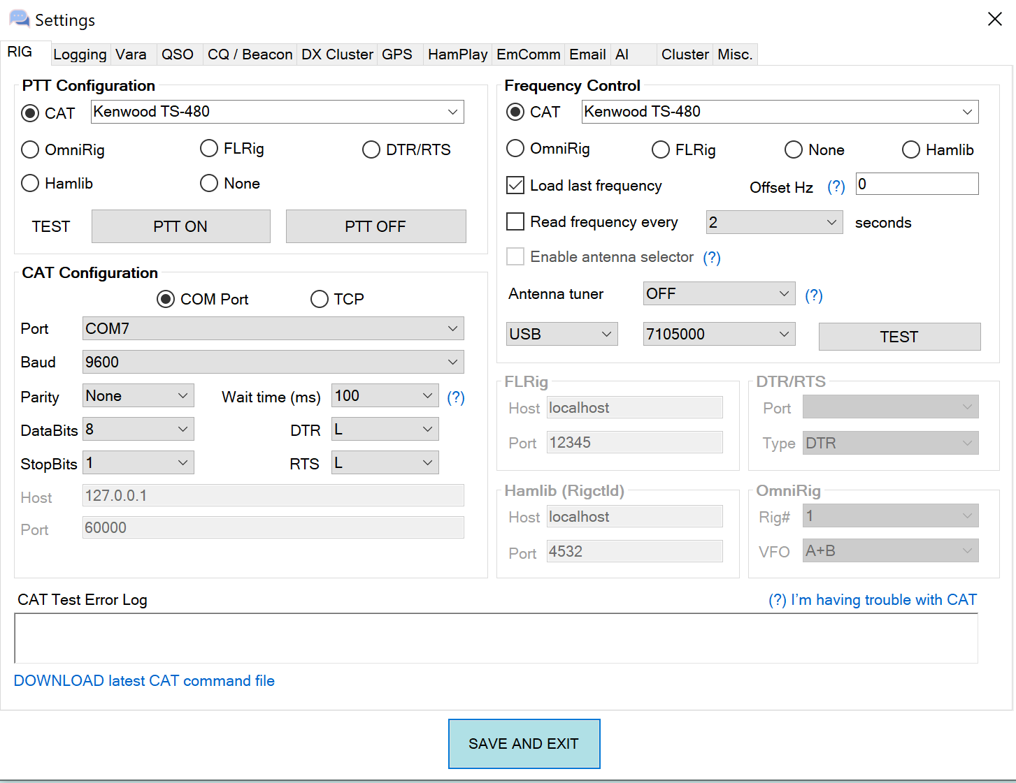
Please see screenshots below for setup configurations.
**Vara AC rig setup matches baud rate. When I hit test buttons nothing happens but I do not get error messages either. When I test CAT control nothing happens.
A decades-long TS-830S user, I recently purchased a 480SAT and 590SG, so that hams in my club won’t be embarrassed to talk to me /grin/. It’s a journey, that’s for sure. I purchased cables in anticipation of getting the radios, so I had done some research. Now with the radios in hand, I have more questions. In this image “digirig - Kenwood TS-480 cable schematics - TM480 0102.png”, which I drew on spec, so to speak, I wonder at the meaning of RIG_AFOUT and RIG_TXD. It seems pretty obvious that these mean audio and RS-232 signals sent from the digirig box to the rig. The Kenwood docs are confusing, sometimes calling for DB-9 pin 2 to be RXD, again, RXD data output (yes), and again “RXD1 data input from PC/IF)”. I suppose that digirig has a lock on what /they/ designed, so the question is: is RIG_RXD data /from/ the COM port /into/ the digirig box? If so, that defines the data flow for the COM port as data transmitted from the 480 COM port on pin 3. The Kenwood service manual shows, using arrows, RD1 /leaving/ the COM port. Elsewhere, the manual says RXD is data /output/ AND, contrariwise, RXD is data /input/ from PC/IF. So not clear to me. If this schematic is what digirig supplies, and hams have found that it works, then the 480 DB-9 pin 3 is output from the rig, despite comments in the manual schematic saying data input.
I looked further…that service manual is long! and discovered
J201 (COM)
1 NC - NC
2 RXD O Data output ****** output !
3 TXD I Data input
4 NC - NC
5 GND - GND
6 NC - NC
7 RTS I Request to send signal
8 CTS O Clear to send signal
9 NC - NC
p 120 X57-663 (A/2) 1/7 apparently pin 3 TXD > ADM202EARU…
RS-232 level converter > TTL RD1
ADM202EARU RS-232 level converter (10) TTL TD1 > RS-232-2 RXD
So pin 2 RXD is /from/ 480 !!!
This is the problem with both the “standard” and with just copying stuff down without taking stock of its real impact. Kenwood would have done us all a favor if, in addition to labeling the COM port with standard names, they had written the actual signal directions. I’m sure I’ve seen that in other Kenwood manuals.
For example, in the “digirig - Kenwood TS-480 cable schematics - TM480 0102.png” above, digirig could have named RIG_TXD DIGIRIG_IN. RIG_TXD can be interpreted 2 ways: as being transmitted from the RIG (correct) or, because it is a digirig signal name, from digirig. Not clear. But DIGIRIG_IN is. I have done the same thing myself: named something during dev, because, of course, I know exactly what it means at the time…only to “discover” much later that I am left with some sense of confusion. /This/ particular issue is made worse by the sloppy way that various manufacturers name the pins on a DB-9 for RS-232. Well, the ADM202EARU RS-232 level converter, pin 10, is unambiguous. See the schematic, p 120 in “Kenwood TS-480SATHX Instruction Manual B62-1735-50 2016----u12.pdf”. That’s my name for it, but that name contains the manual ID and date.
Yes, there is ambiguity in signal names when perspective is not given. For that reason, all Digirig’s signal names are given from the perspective of the radio (RIG) with corresponding prefix added. Some examples:
RIG_AFIN - audio input of the radio such as mic or line in.
RIG_TXD - serial data output from radio
As far as TS-480 goes, the cable offered in store for this radio is known to work and you are welcome to refer to the schematic in the product listing to clarify the situation with the pinouts.
Good morning! "all Digirig’s signal names are given from the perspective of the radio (RIG) " I had /not/ seen this before, so for the past few years I have wondered about the names and what then mean. As for the cable, I came here because I was having difficulty determining what USB to DB-9 RS-232 cable I should buy. I didn’t see one on the site, but I looked at the other TS-480 products and the forum because I thought that you helpfully include schematics (thanks), and I’d be able to see from discussions what the signals are. Not so, until I read the explanation of how digirig names signals. On one of the posts about the TS-480, there is a comment to the effect of “if this doesn’t work, I have one with the alternate wiring, and that should work”. That bit of fuzziness is why I continued to explore the Kenwood TS-480 Service Manual until I found unambiguous indication of signal flow. Even that manual is not entirely consistent, but chip specs aren’t fuzzy, and they settled the matter in the end. I posted here, and will post in groups.io, thinking that the more places (factual) knowledge is posted, the better off we all are. The ADM202EARU RS-232 level converter unambiguously shows signal direction.
If you only need the serial connection then you can look for RS-232/DB9 USB dongles. TS-480 has the most common pinout so the chances are it will work out of the box. Some Yaesu transceivers have reversed (null-modem) pinout. Something like that can be corrected with a null-modem adapter.
If you also use audio/PTT for the complete integration of the transceiver with the computer, then you can use Digirig Mobile in RS-232 configuration and off-the-shelve TS-480 cable kit.
To be clear, I have the digirig TTL, RS232, and the mini, as well as cables for my radios (Still missing that TS-830S cable /grin/). It all works splendidly. True, all I came here for this time was information, and that led to the confusion I mentioned earlier. I am glad you mentioned “Digirig’s signal names are given from the perspective of the radio (RIG)”, because I can now apply that bit to all the schematics.
But I disagree with the quoted part of your last message. The TS-480 has a male DB-9.
All RS232 devices that use a DB-9 connector should conform to the standard TIA/EIA-574.
DCE (Data Communications Equipment) female DB-9 or
DTE (Data Terminal Equipment) male DB-9
As you see from the table below
Pin Signal Signal Name DTE DCE
1 DCD Data Carrier Detect In Out
2 RXD Receive Data In Out
3 TXD Transmit Data Out In
4 DTR Data Terminal Ready Out In
5 GND Ground - -
6 DSR Data Set Ready In Out
7 RTS Request to Send Out In
8 CTS Clear to Send In Out
9 RI Ring Indicator In Out
pin 2 should receive data, not transmit. To make matters worse, various manufacturers are not clear about the data direction of their devices. I just purchased a cable that I was assured met the data requirements here, only to find out when I got it that it did not. So, IMO, much of this is a guessing game, which is why I a) came here for info, b) did the search on the schematic, and c) continued to write all this. The latter, with the hope that it will benefit those with the same questions.