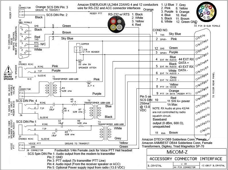
I have been working on interfacing the MiCOM-Z to external modems and devices. I am using a SCS modem as the reference but this can be applied to any external modem. Using Bonnie KQ6XA MiCOM 2 & 3 drawing as a starting point. Tom the Chief Tech Engineer of Royal Communications has also been a great source of knowledge. This is a work in progress but I do have an operational prototype breakout board and am just starting to put together a final hardware version. Yes, there are a lot of connections and one may not want to apply everything. The main difference is the use of pin’s 43 and 44 for the Rcv Audio. These are not part of the squelch circuitry as are pins 4 & 5. Another change I made was to bring V+ out to the external connection as it offers 13.8VDC at 1A max.
There are some tips and tricks (e.g. laying down the 10uf DC blocking caps so that you can close the lid on the project box and the use of solderless DB9 and DB44 connectors. Another Royal Communication input was to use the Triad SP-70 audio transformers for low distortion and small footprint.). I will offer this draft as a potential consideration for others who want to interface like MiCOM radios and ATU. There is V+ over the coax line from the radio to the ATU. At least my unit does as it provides power to the CP-125M ATU.
For what it’s worth, I like the idea of scanning multiple frequencies and bands to form a primary connection front end to any modem or radio. The MiCOM can scan 4-5 frequencies in 1 second or less. Once the connection is established, then the data transfer or voice communications follow until completed/cleared.
Nice looking design. I never bothered with using the balanced audio for Micom’s (2RS and 3T) for SCS or other digital modes. Granted, I didn’t use a Digirig, as they didn’t exist then!
RM500 and RM1200 amps and RF382 ATUs. V+ shouldn’t be active if the ATU isn’t connected, as you can connect the Micom directly to broadband antennas where V+ would get spent in terminating devices (OPTS ACC NONE.)
Thank you for the response Matt. I am still a newbie on the MiCOM-Z system. For me, I do have an ATU that uses the V+ voltage. It is a beast of a box, and according to Tom at Royal Communication, is a very robust ATU. It is extremely fast to meet the demands of ALE.
I have just started to build the final version of the modem interface board with the better audio transformers. Applying lessons learned as I go.
I do see your call on the LQA sounding directory.
I am unsure where to set my FSK/PSK audio levels to on AirMail. The commercial radio’s seem to have a much higher value compared to ham radio’s. More testing to follow.
Lastly is cracking the radio case to see about changing the R44, on the Lord Board, to lower the speaker audio. The 2011 online service manual does not show the component as it is too old. My MiCOM-Z has a 2018 build date. One sure way to find out is to crack the case.
I doubt you will use FSK (P1) so decide if that mode is wanted. If not, then PSKAmpl is the only setting you will manipulate.
You might also want to insert a pot into the audio drive line going to the radio for manual adjustment. If you want hands off, set it once operation, of course don’t bother.
Setting FSK/PSK levels with a Micom is “best effort.” I’d recommend turning off the V+ as previously mentioned so that you can place a power meter and termination to the radio. Choose the highest power level you plan to operate, i.e., MED.
Familiarize yourself with the amplitude section of the manual. Note that Micom’s use positive ALC, however, without an amp or another circuit, it will not function as there are several lines involved with ALC/AMP operation.
You should choose the desired output power level. Micom’s that are not cooled should not be ran for long periods at max power. They specifically have cooling trays if this is needed. A bare Micom that is planned for 15 minute or longer transmit sessions should observe the 50% derate rule (60w.)
In my experience, the easiest procedure is to set PSKA from 140 to 50, run U 3, and increment PSKA by 10 as you monitor the output power. If you have set TX power to MED, you should be able to drive the radio to 60w. Once you reach this level, back PSKA down 10.
As the world turns, and systems evolve. I am in the market for a fast tuning ATU for ALE operation. The Motorola CP-125M is being used with a Barrett 4050ip.
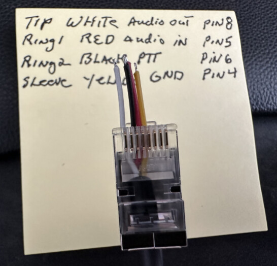
I also need to get on FLDigi MT63 and am thinking of using the Mic RJ45 connection for the Digirig. It has all the functions needed (Audio out, Mic Audio, PTT Mic and Gnd). Hoping that will do the trick.
Please correct me if I am in error, Audio Out and Audio In pin Digirig labels are from the perspective of the transceiver. The MiCOM-Z PPT line transmits when the pin goes low (GND). Right now, that is not working for me. I have FLDidi PTT set as Hardware with RTS com11. Most likely operator error(me). Keep in mind that MiCOM has pin 8 on the Left of the RJ45 (White).
I am very happy to report that the Digirig Lite works very well. Both RCV and PTT via the MiCOM-Z Mic RJ45 interface within the FlDigi application.
I must admit to a newbie move. When I plugged in the PC side, I was getting both Green and Red constant LED’s and no RCV. Even tried different cables. Then I realized that the TRRS connector was not inserted all the way. Doah!! That would do it. Now the “normal” Green LED and only Red when transmitting.
Very clean setup if I might say.
In Fldigi: Configure > Config Dialog > Rig Control > C-Media PTT
Check the Use C-Media PTT box
Select C-Media-A (could also be C-Media-B) in the C-Media device dropdown
Select GPIO-3 in the GPIO line dropdown
Click the Select button
Click the TEST button to verify PTT works
Click Save, then Close