Trying to get Digirig Mobile, CM108 PTT on Linux to work

I’m trying to get my digirig mobile (PCB v1.9) to work with Direwolf and a Baofeng radio from a Raspberry Pi. I have the Baofeng HT Digirig Cables Set from Digirig.

I’m unable to get the PTT function to work. I’ve ensured the /dev/hidraw0 device is set to rw permissions for the user running Direwolf (I’m using group audio, my user and direwolf user both are members of group audio, group audio has rw permissions to /dev/hidraw0). I have set a PTT CM108 line in my direwolf.conf. Direwolf never keys the radio.

I’ve tried using the cm108 tool included in direwolf (v1.7). Running that as
cm108 /dev/hidraw0
shows it toggling between 0 and 1. Radio is still not activated. Measuring voltage or continuity/resistance between GND and PTT on the two-pin Kenwood connector with a multimeter shows no change when cm108 toggles ptt state.

What am I missing?

Thanks
Hrafnkell TF3HR

Output from cm108

he@tnc:~/direwolf/build/src $ ./cm108
    VID  PID   Product                          Sound                  ADEVICE        ADEVICE            HID [ptt]

    ---  ---   -------                          -----                  -------        -------            ---------

**  0d8c 013c  USB PnP Sound Device             /dev/snd/controlC1                                       /dev/hidraw0
**  0d8c 013c  USB PnP Sound Device             /dev/snd/pcmC1D0c      plughw:1,0     plughw:Device,0    /dev/hidraw0
**  0d8c 013c  USB PnP Sound Device             /dev/snd/pcmC1D0p      plughw:1,0     plughw:Device,0    /dev/hidraw0

Permissions of /dev/hidraw0

he@tnc:~/direwolf/build/src $ ls -l /dev/hidraw0
crw-rw---- 1 root audio 242, 0 Nov  5 17:29 /dev/hidraw0

My udev rule for hidraw permissions

he@tnc:~/direwolf/build/src $ cat /etc/udev/rules.d/99-direwolf-cmedia.rules
SUBSYSTEM=="hidraw", ATTRS{idVendor}=="0d8c", GROUP="audio", MODE="0660"
PTT CM108

is for Digirig Lite. Digirig Mobile uses PTT by RTS.
With Digirig Mobile it should be something like

PTT /dev/ttyUSB0 RTS

1 Like

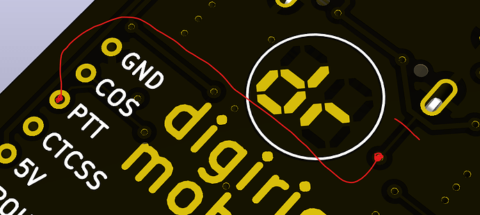
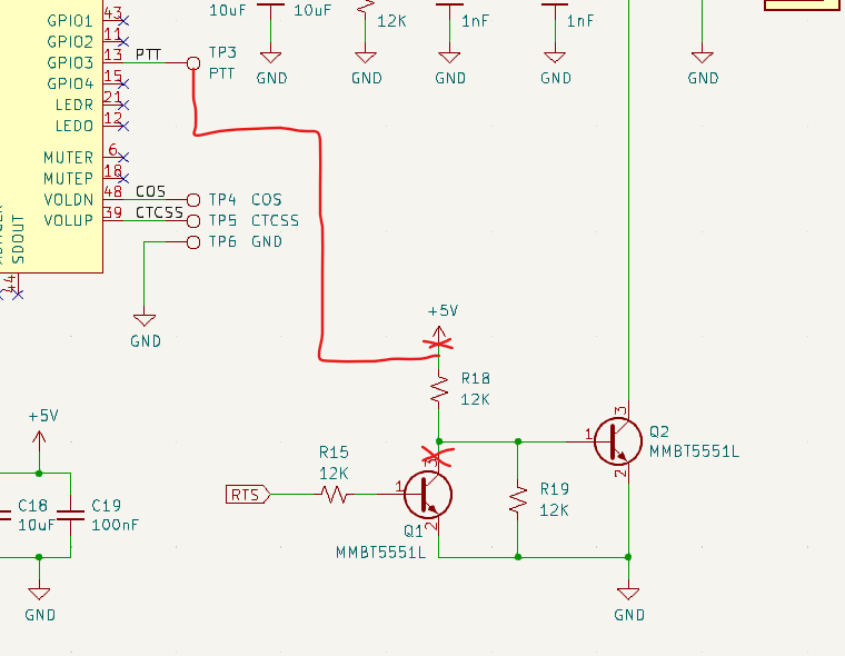
Thank you. I was just looking at the schematic of Digirig Mobile and realized this. The GPIO 3 PTT signal is just connected to a test point. The RIG_PTT line is driven by RTS!

1 Like

This setup works well now.

1 Like

I was just having the same issue and started looking for answers. The issue with using RTS for PTT is that it ties up the serial port and makes CAT control or other serial data unavailable for use by any other apps. For example, I am using Direwolf and it is configured to use RTS (because that is the only option). However, the radio (Yaesu FTM-500D) is able to provide serial output for GPS or decoded AX.25 packets, but since the serial port is already in use for RTS by Direwolf I am not able to access this data with a terminal program or a logger.

So, if one wanted to switch a Digirig Mobile to use GPIO3 from the CM108 for PTT instead of RTS, thus freeing up the serial port for other uses, what would be the recommended way to do that?

My inclination would be to remove R15 and run a normal human-sized 12K resistor from the GPIO3/PTT pad to the base of Q1. Is there an easier or better way?

With GPIO3 there is no need to invert the signal as it is with RTS so you’ll be tapping base of Q2. Refer to the PTT implementation in Digirig Lite for example:

digirig-lite-1_2-schematic.pdf (158.9 KB)

You may be able to avoid hardware mods altogether by splitting the COM port in software. Haven’t tried that personally, but I see some promising results by searching for “serial port software splitter”.

So I tried a few port splitters and had mixed results. The free ones do not allow for restricting access to the flow control lines, and the commercial ($$$) ones do not go far enough in doing so - and cost more than the digirig itself does. I really would like to completely block the ability for any app to assert the RTS line. Simply opening a serial port causes RTS to go active, and unless the app itself clears RTS it will trigger a continuous transmission.

I would like to discuss further the hardware options for doing this. Shall I start a new thread or would it be appropriate to continue here?

We can continue here. The hardware mode will require some precision soldering on your part, but it’s possible with the right equipment and patience.

My previous comments regarding modifying the circuit board were based on looking at the schematic. I have since removed the board from its enclosure and now I see just how tiny these parts are! My soldering iron was considered fine tipped about 30 years ago, but today it looks more like a sledgehammer. I may need better tools to carry this out.

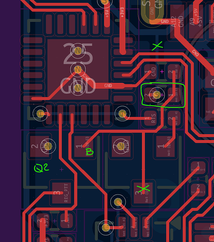
Looking at the top of the board with the USB connector on the right, I see Q2 at the top edge and Q1 just below it. Fortunately these transistors have among the largest contacts visible on the board. I have board revision 1.11 for anyone from the future reading this.

Regarding disabling the ability for RTS to trigger transmit, my initial thought was to remove R15 but I see a very short trace on the top of the board from the base of Q1 to R15 and it looks like I may be able to cut it with the tip of an xacto blade. What would you recommend here?

Then to switch to using GPIO3 from the CM108 to trigger transmit, I see that the Digirig Lite has a rather different PTT circuit than the Digirig Mobile does, using a 1.5K resistor to drive Q3 on the Lite instead of the 12K used for Q1 on the Mobile. Would you recommend connecting GPIO3 to the base of Q2 through a resistor, or something else?

Yes, resistor is required when applying voltage to base to limit the current.

I would approach it like this so no additional parts would be required:

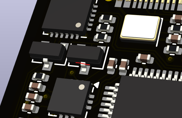
Disconnect Q1 by popping the lead of the board or clipping it.

image

Cut 5V trace and connect PTT line to via

Here’s the area of interest:

1 Like

Thanks for the info!

I have modified lots of circuits in the past, but none at this small scale. Disconnecting the collector of Q1 looks relatively easy. Cutting the 5V trace and soldering to the via looks a bit more difficult not only due to the size but also because of the solder mask covering them both. This has renewed my interest in seeking a software solution.

In a prior post I was a bit too hasty in declaring that the free serial port splitters do not allow for restricting the flow control lines. I did some further work with com0com and have come up with a configuration that almost works. I have successfully isolated RTS control to a single virtual serial port but have not been able to get the serial data flowing the way I want it to. I will post the solution here if I get it working. If only it had better documentation…

1 Like

This is what I have come up with for sharing a serial port with the free com0com software. It would have taken a lot less time to just do the hardware mod that K0TX so kindly provided, and I may still do that, but something like com0com would still be needed to do everything I wanted to do. Isolating the RTS line was the added challenge for this exercise, and the hardware mod would have eliminated that. Direwolf is the only application I know of (on Windows) that is able to use a GPIO pin for PTT,

Granted, this solves a problem for only a very specific set of hardware and software, but if anyone happens to have a Digirig Mobile connected to a Yaesu radio with a combined audio and serial interface in a 10 pin DIN connector configured to send GPS output through the serial port, and want to use the Direwolf soundcard modem along with an additional APRS mapping program, then you may find this useful. This has been tested on a Windows 10 system.

First, in the com0com setup command prompt, do this:
--silent uninstall (to clear out any previous config and start fresh, if desired)
install 0 PortName=COM20,EmuOverrun=yes HiddenMode=yes
install 1 PortName=COM21,EmuOverrun=yes HiddenMode=yes
install 2 PortName=COM22,EmuOverrun=yes HiddenMode=yes

This creates three virtual serial port pairs: COM20/CNCB0, COM21/CNCB1, and COM22/CNCB2. There is nothing special about these COM port numbers, just choose ones that are not already in use on your computer.

Then use hub4com to perform the routing between these ports:
hub4com.exe --load=,,_END_
--baud=9600
--route=0:1,2,3
--route=1:0
--create-filter=pinmap,ptt_out:--rts=connect
--add-filters=0:ptt_out
--create-filter=pin2con,ptt_in:--connect=cts
--add-filters=1:ptt_in
--ocrts=off
COM6
\\.\CNCB0
\\.\CNCB1
\\.\CNCB2
_END_

What this does is send the serial output from COM6 (where my Digirig is) to all of the virtual serial ports COM20, COM21, and COM22. The only port which is allowed to set RTS is COM20, so any other programs which open COM21 or COM22 cannot cause undesired radio transmissions.

The Direwolf config needs these lines (and more, these are just the serial related ones):
GPSNMEA COM21 9600
CHANNEL 0
PTT COM20 RTS

Then an APRS or other mapping app can be connected to COM22 for its GPS.

I wanted to also allow for CAT control on a free COM port but I have not been able to create a hub4com routing configuration which allows for any port other than COM20 to send data to the radio while maintaining the RTS isolation that was required. If anyone knows how to do this, please let us know!

73
AD5OO
Dave Rivenburg