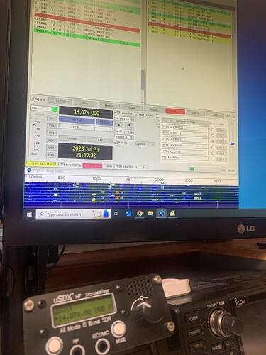
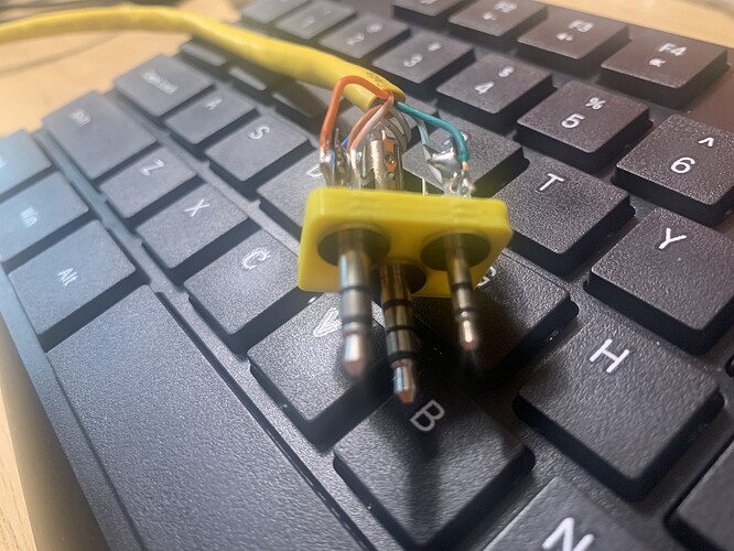
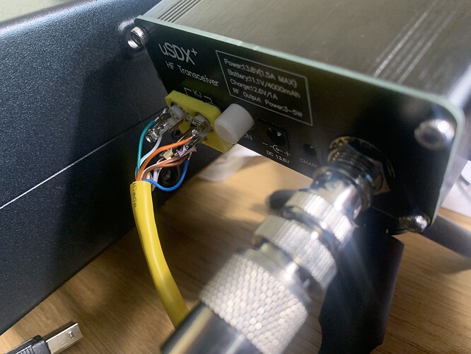
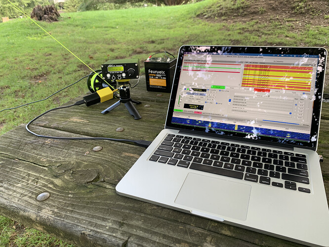
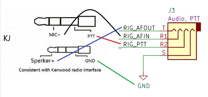
PTT is through the Audio cable of the digirig, not an external sound card. I have no idea if there’s a CAT command for PTT, but I’m sure the Kenwood specs are out there on the internet.
Friends, I’m sorry. I understand everything. You are using DIGIRIG MOBILE. A device that combines an external sound card and a PTT switch. Alas, this device is not available in my country. Although the price is very high…
I want to work with such a device. I will try to create it myself…
I’ve built my interface and it is working great. I didn’t have any difficulties regarding CAT PTT, everything work flawlessly for me. The first contact was from Italy!!!
*** I can’t add more reply. The system limit me to 3 reply per topic ***
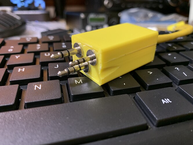
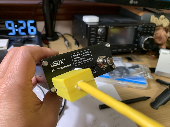
The files are shared on Thingiverse here. It is a quick and dirty design, everything is glued together. I might make a better version in the future, like snap together parts, etc.
I think it’s great you printed an all-in-one plug. Have you shared the design on online? I’d love to try making one like it.
A wonderful device.Thank you very much for sharing it. I understand that you use DIGIRIG, do not directly connect to the computer?
We are also limited to 3 messages!!!
I’ve gain access as a member and no longer limit to 3 reply!!!
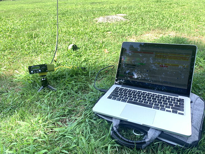
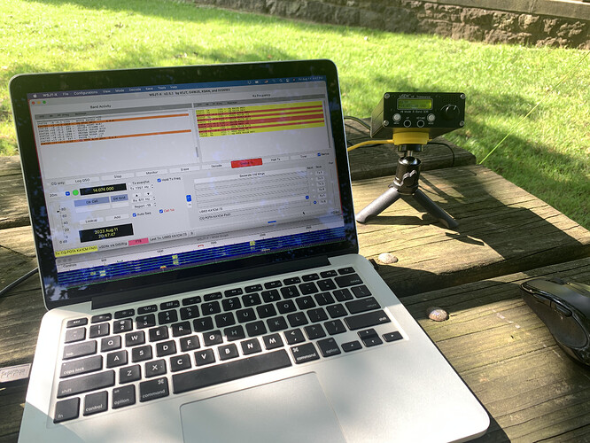
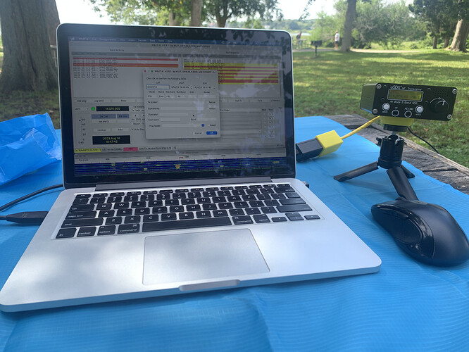
I’ve gone out POTAing with wonderful success. At least 4 activations went well with FT8 and CW.
Congratulations! Great photos, and I recognize the yellow cable with your custom plug for the uSDX+
73 Constrainted
Awesome project! Can you share the pin-outs, both ends, for each of the connectors, please?
Thanks!
I’m still trying to figure out the wiring from the 3-connector uSDX-8 to the 2-connector Digirig (rev 1.9).
uSDX-8
KJ Mix/PTT 3.5mm connector only uses 2 of 3 pins (Center - Mic, Base - PTT)
KJ Sperker 2.5mm connector also only uses 2 pins (Tip - Speaker, Base - Ground)
Mic/Key TRRS uses all 4 pins (Tip - RXD, Outer Ring - TXD, Inner Ring - SEND PA, Base - Ground)
Digirig
Audio 3.5mm - Tip - ?, Ring - ?, Base - ?
Serial TRRS - ? ? ? ?
Thanks!
CAT is a straight TRRS aux cable.
The digirig schematics have all the details you need for the TRRS end of the audio cable. The schematic for version 1.9 is here: Digirig Mobile Rev 1.9 – digirig. Since these don’t change as new digirig versions are released you should be OK to use that schematic even if you have an earlier version.
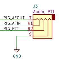
For the 3-connector Chinese 8-band uSDX are you saying that a straight-through 4-pin TRRS cable alone is all that’s needed for complete control and audio?
If not, how is the Audio port on the Digirig pinned to the 3.5mm and 2.5mm “KJ” labeled connectors, please?
I’m confused as to what “CAT ONLY” means and to which model of uSDX rig this applies.
What will this cable wiring not allow me to do, please?
I need to be able to operate all of the digital modes, especially via fldigi and JS8Call.
My rig has the 3-connector layout on the back (one of which is labeled “CAT”, the TRRS connector), but this diagram doesn’t use the rig’s “CAT” connector at all.
Thanks.
I’m not sure how much clearer I can make this. If the back of your transceiver look like what I posted earlier in this thread then you can work digital modes (WSJT-X, JS8-Call, fldigi, etc. with the correct cables.
The AUDIO cable only handles audio and PTT. The CAT ONLY connection is only needed for rig control.
You don’t need the CAT connection…you can set the frequency and mode by hand. That’s how the digirig is used with most (all?) handhelds and with radios like the FT-891 which connects directly to the computer for CAT control.
OK, I’ll set the 3-connector shell aside and try the 2-connector cabling and see how it works. Thanks.
I wish you had said earlier you were trying to build a 3 connector shell.
KA1CM’s custom cable is simply a replacement for the 2 cables you normally use (Baofeng data cable and TRRS aux cable). It isn’t pictured, but the other end of the cable has 2 TRRS male connectors that plug into the digirig. if you look closely at the last photo KA1CM posted you can see the 2 connector end mated with the digirig.
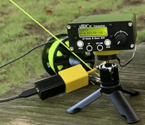
It wasn’t apparent to me what the closed yellow shell at the Digirig contained.
Thanks!
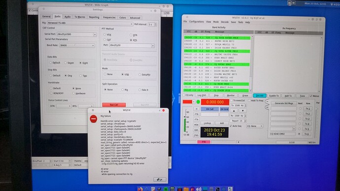
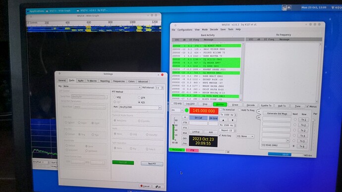
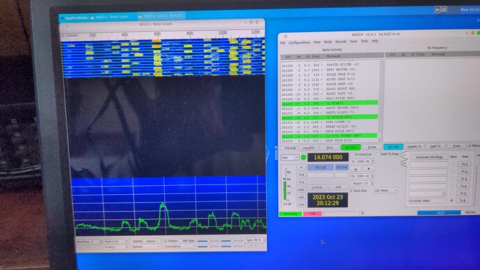
As you can see the receive side is showing band activity but the WSJT-X Wide Graph is blank.
Can you spot the settings I have wrong, please?
Should PTT be set to VOX or ?? (NOTE: I’ve never used FT8 before. Do I need to click Enable TX?)
With the settings window open the frequency is, oddly, shown as 2m.
When I click OK and that window closes - I can set the band to 20m and the WSJT-X Wide Graph starts to populate.
Should I be seeing voltage between Mic & PTT (7.5v with PTT positive and Mic negative) and from all three pins to ground (at the far end TRRS at the Digirig)?
