Hi has anyone utilised the COS Pin on the Board to maybe invoke a VOX PTT function and Make this work with Allstar ?..
I am going to guess its PTT High but was looking to see if the COS could be used to Drive a PTT when Audio is Received or if additional Components would be required.
I also realize that any warranty potentially goes out the Window
Rob,
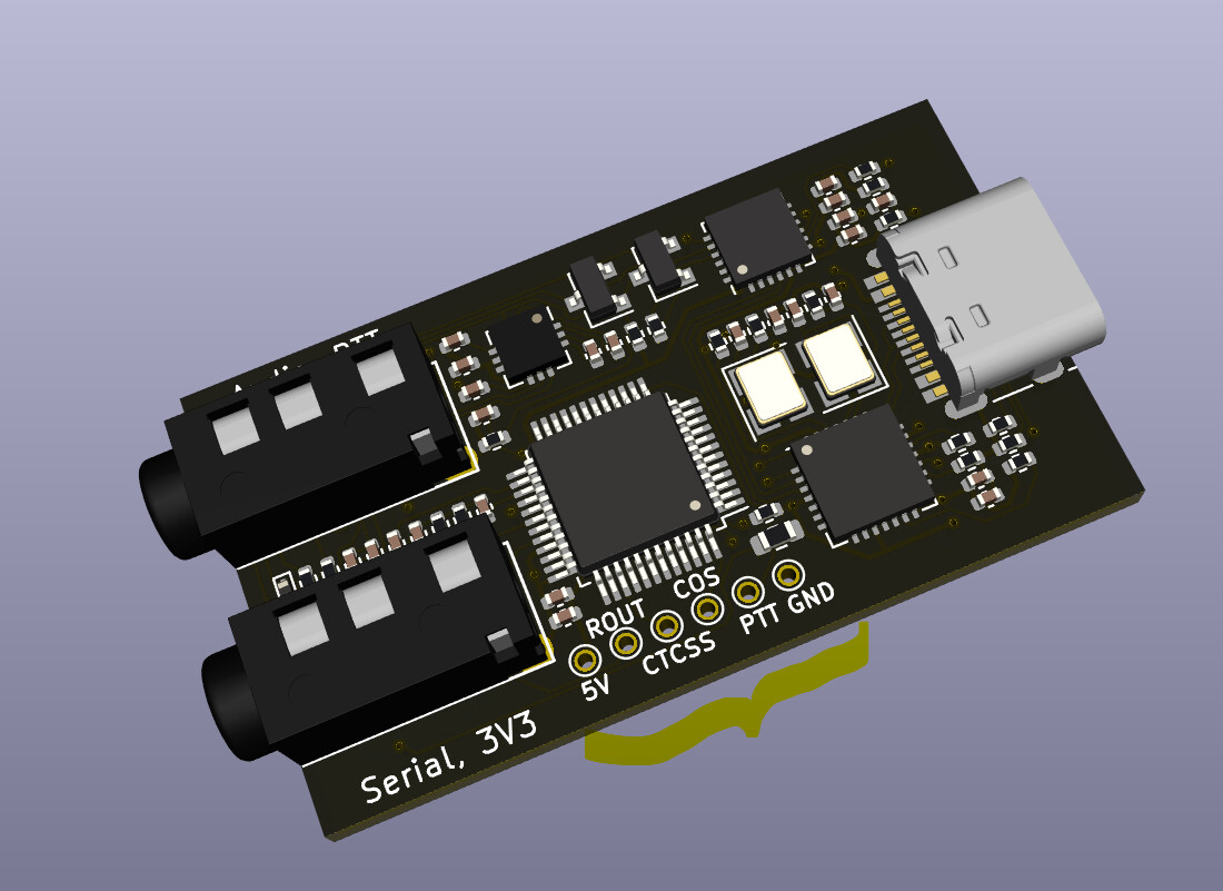
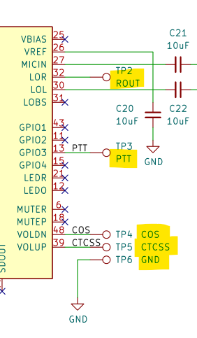
I routed COS and few other signals from CM108 specifically to simplify Allstar projects. Haven’t received any reports so far. Please post your findings here.
AllStar has a DSP level detector (ie. Receive Carrier Detect) feature that works perfectly, is easy to enable, and makes a COS line totally unnecessary. The below guide discusses this in detail:
The Digirig Mobile then ends up being the perfect AllStar interface for HTs because the only 4 lines that are needed (Tx & Rx Audio, Gnd, PTT) are all on the one 3.5mm TRRS.
There is much confusion surrounding the “hardware” COS and CTCSS inputs to the CM1XX chipsets. Here is a dissertation I wrote some time ago, that hopefully explains the situation well:
The COS and CTCSS logic inputs on CM1XX based radio adapters were originally the volume-up and volume-down functions, actuated by manual (push button tactile) switches in a standard audio adapter (FOB). These inputs are internally pulled high, to 3.3 V, and have to be pulled low enough to become valid. As such the push-button switches made a good ground when depressed, as that’s what the other side of the switch was tied to - ground. Most AllStar radio adapters use protection diodes (BAT-43’s) that don’t allow voltage to be sent into the CM1XX chip. If voltage is allowed to be inputted to these pins, the chip is immediately destroyed. So - with the diodes in place, it doesn’t matter what voltage is present on the COS or CTCSS hardware inputs, because voltage on these pins doesn’t make anything happen, and, because of the protection diodes, doesn’t hurt anything if voltage is present. Pull-up resistors are totally unnecessary, because we need a ground to assert the condition. Any reference you see to “active high” or anything indicating the COS and CTCSS signals need to go high to become valid is technically incorrect. A diode is like a one way valve in a water supply - it simply allows current to flow in one direction - not the other. Diodes do not invert the logic applied - they simply provide a path in one direction - to ground.
Okay, so the CM108/119’s logic inputs are looking for a ground to be valid. This “active low” condition is required NO MATTER if the setting in the ASL conf file is upright or inverted. So - the setting in the configuration file doesn’t change the fact that the adapter needs an active low to be valid and assert the condition. All this software setting does is change if the low condition exists when the radio is hearing a signal, or when it’s not. Using a DMM, you can read the voltage on the CM1XX side of the BAT-43 diodes to see if the logic level is properly changing from 3.3V (or there abouts - depending on the exact chipset) to 0.0V or a few tenths of a volt.
Not all radio logic signals are created equal. Some logic circuits can source current, but lack the ability to sink. Sometimes active high circuits (circuits that provide a voltage when the state becomes active) don’t have the ability to pull to ground very well. These circuits may not have the capability to pull the COS and CTCSS inputs low enough on the radio adapter to become valid/active. A pull-down resistor can help, but nothing beats a real active low circuit. A 2N2222 (or similar NPN transistor - - open-collector) with its emitter grounded usually works well. Use the collector to feed the radio port connection and adequate bias through a resistor to the base (1-10k) to the active high source. This bias action saturates the transistor and it essentially shorts out causing a switched ground to appear at the collector when bias is present.
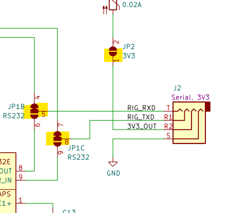
One other note re. AllStar. I just noticed the PTT line on the Digirig audio TRRS connector is keyed by the RTS line from serial interface IC – not the PTT line on the CM108AH. Therefore to make this work for AllStar may not be as simple as plugging in a single TRRS cable as I mentioned above. Not sure if the Digirig board allows the TRRS jack to be connected to the CM108 PTT easily or if you would have to cut traces on the board and solder a jumper wire? If so, and after having done a lot of testing with CM108AH fobs (which are available now with AH suffix ICs), Repeater-Builder RIM-Lite V2’s and Masters Comms DRA-30s, the Rim-Lite V2 may be the best option for AllStar considering the overall audio quality, RFI resistance, cost, and availability of all needed lines on one connector.
Yes, CM108’s GPIO line which is used for PTT in the fobs is available for easy tapping and can be bridged to the TRRS connector. It would be a more elegant solution to have PTT by RTS option added to allstar implementation, but even with the mod Digirig is a simple (comparing to USB fobs) and cost effective (comparing to other interfaces) option.
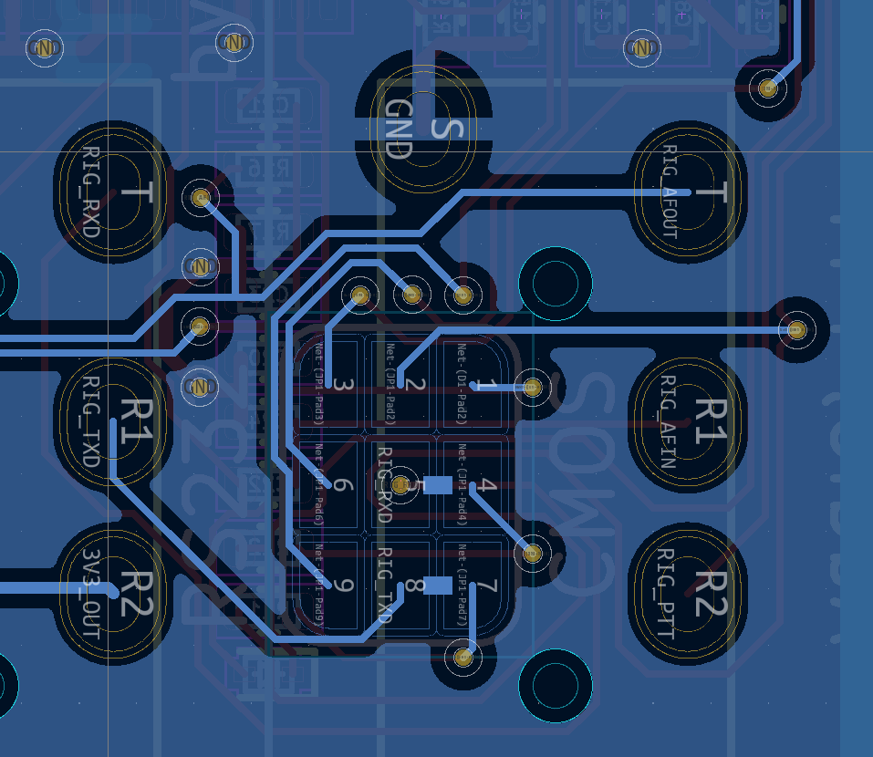
Sounds good, is there a picture or other file on the digirig site that shows all the pads / solder jumpers for the TRRS jacks? Didn’t see that on the site anywhere but would be nice if both jacks could be easily jumped to provide any needed lines. Would also be nice if the COS input could be jumped easily to one of the TRRS jacks as many ASL configurations do use hardware COS.
ASL should be able to be configured using its events system to toggle an RTS line but that would require non-trivial config file changes thus a solder jumper would be simpler. Thanks, NR9V
Thanks for your quick reply! That image explains it all, and more. Is there a file from the github repo I could have loaded into KiCad to produce that image? Thanks.
@davidgsd Forgive me, but I have read this several times, and while I understand having to uncomment the two lines, I don’t see specific instructions how to get it done.